Seat track for vehicles

a seat track and vehicle technology, applied in the field of seat track for vehicles, can solve the problems of deterioration of locking strength, failure of locking between the fixed rails, and weak points in the locking structure of the conventional seat track, and achieve the effect of reducing frictional for

Active Publication Date: 2005-04-05
AUSTEM CO LTD
View PDF15 Cites 50 Cited by
  • Summary
  • Abstract
  • Description
  • Claims
  • Application Information

AI Technical Summary

Benefits of technology

Therefore, the present invention has been made in view of the above problems, and it is an object of the present invention to provide a seat track for vehicles, which is configured in such a fashion that a fixed rail and a movable rail thereof come into point contact with each other by means of balls during their relative movements, thereby achieving a reduction in a frictional force between their facing surfaces, and furt

Problems solved by technology

The conventional seat track as stated above, however, has a weak point in the locking structure thereof.
As a result, the locking protrusions fitted in the fitting holes 112 formed at the bead portion 111 of the fixed rail 100 are unintentionally released therefrom, resulting in a failure in locking between the fixed rail 100 and the movable rai

Method used


Image

  • Seat track for vehicles
  • Seat track for vehicles
  • Seat track for vehicles

Examples


Embodiment Construction

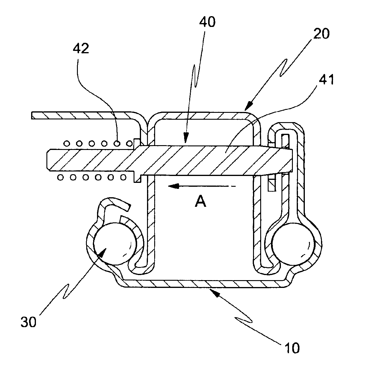
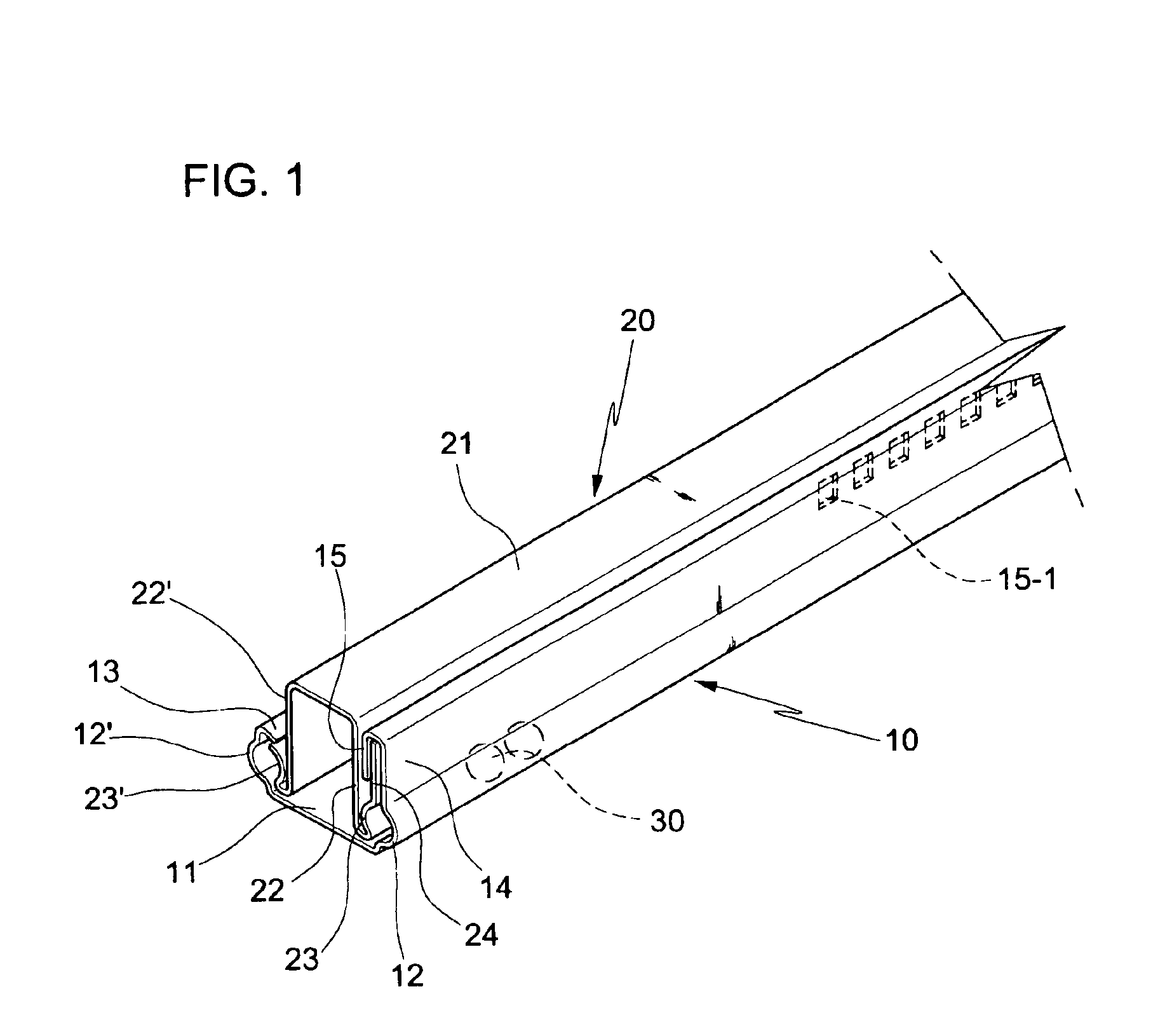
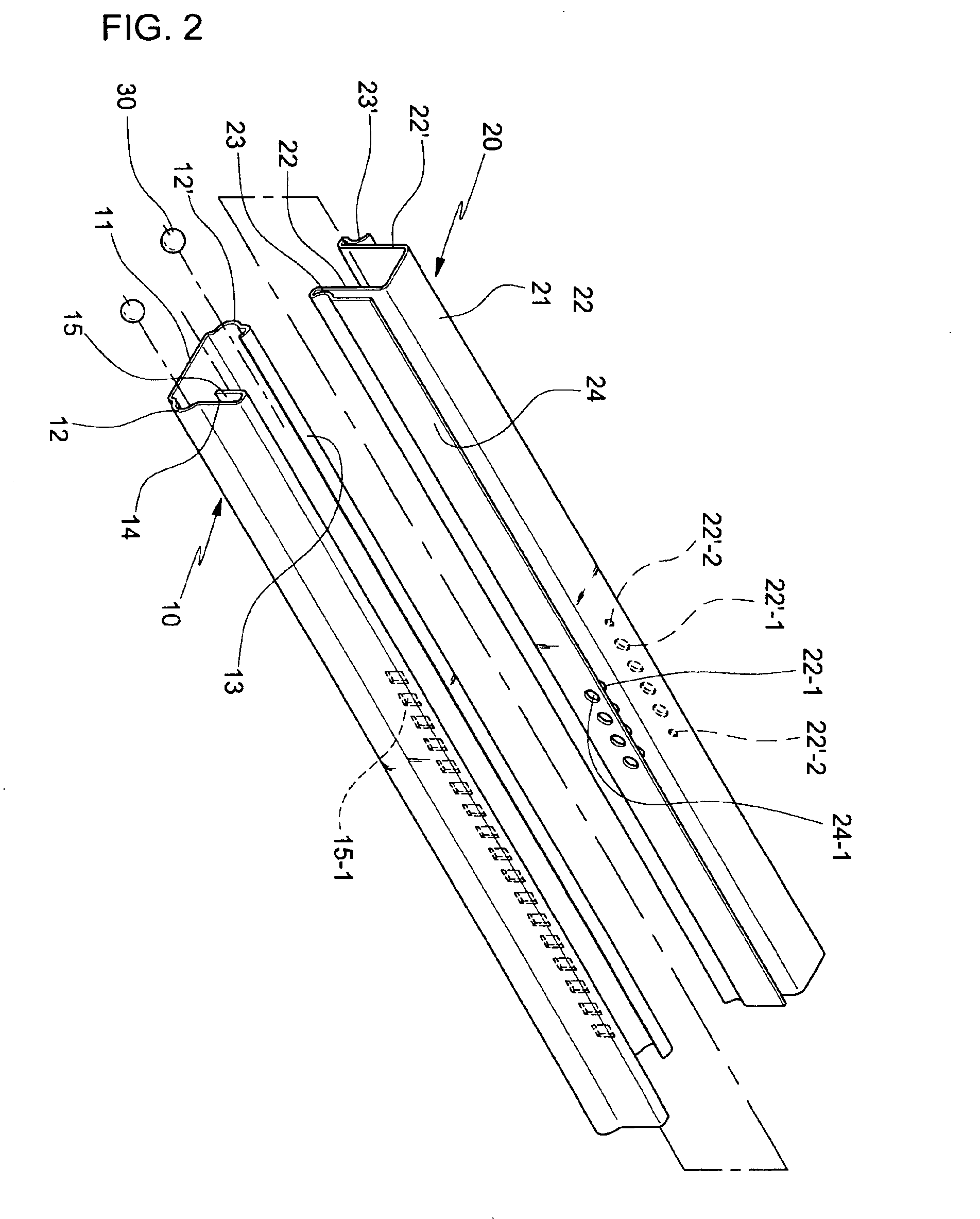
FIG. 1 is a perspective view illustrating a part of a seat track in accordance with the present invention, in a state wherein a movable rail and a fixed rail thereof are coupled to each other. FIG. 2 is a perspective view illustrating the seat track of the present invention, in a state wherein the movable rail and fixed rail are separated from each other. FIG. 3 is a sectional view illustrating a coupled state of the seat track of the present invention. As shown in FIGS. 1 to 3, the seat track of the present invention basically comprises a fixed rail 10, a movable rail 20, and a plurality of balls 30. The fixed rail 10 is fastened to the bottom plane of a vehicle body by using bolts so as not to move. The movable rail 20 is fitted in the fixed rail 10 while being positioned in the upper portion of the fixed rail 10. The movable rail 20 is adapted to move back and forth in a state wherein a seat for a vehicle is mounted on the upper surface thereof. The balls 30 are located between t...


PUM


Abstract

Disclosed herein is a seat track for vehicles. The fixed rail includes a horizontal bottom fixed piece, a pair of first and second grooves formed by bending both side portions of the fixed piece at a right angle and rounding a center portion of each of the resulting vertical bent portions to have an outwardly convex semi-circular form for allowing balls to be inserted therein, a first end piece formed by downwardly bending a vertical end portion of the second groove by an acute angle, a vertical piece extending upwardly from an upper end of the first groove by a relatively long length, and a second end piece formed by twice bending an upper end portion of the vertical piece at a right angle.

Description

BACKGROUND OF THE INVENTION1. Field of the InventionThe present invention relates to a seat track for vehicles, and more particularly to a seat track comprising a fixed rail, and a movable rail used to move a seat back and forth, which have a structure of enabling a pin type locking device to be mounted thereto, thereby increasing resistance to shock applied from the front or rear side thereof, and of eliminating a bead forming process, which was inevitably performed in the prior art, thereby improving workability, resulting in a minimization of manufacturing costs.2. Description of the Related ArtIn general, seats for vehicles are configured to move back and forth within a predetermined extent in order to secure optimum ride comfort of drivers and passengers. With such configuration of seats, especially, drivers can adjust the position of their seats on the basis of his / her body size, thereby enabling to operate a steering wheel or pedal in the most comfortable sitting posture.Refe...

Claims


Application Information

Patent Timeline
IPC IPC(8): B60N2/08B60N2/06B60N2/07F16C29/04
CPCB60N2/0705B60N2/0715F16C29/04B60N2/0868B60N2/0875B60N2/0825B60N2/07
Inventor OH, BYEONG CHAN
Owner AUSTEM CO LTD
Why Eureka
Try Eureka