Pump system using a control fluid to drive a switching valve mechanism for an actuating fluid

a control fluid and switching valve technology, applied in the field of pump systems, can solve the problems of poor compatibility, poor maintenance ability of the switching mechanism, etc., and achieve the effect of excellent maintenance ability and compatibility

Inactive Publication Date: 2005-04-05
IWAKI
View PDF9 Cites 42 Cited by
  • Summary
  • Abstract
  • Description
  • Claims
  • Application Information

AI Technical Summary

Benefits of technology

The present invention has been made in consideration of the above situation and accordingly has an object to provide a pump system excellent in the maintenance ability and compatibility.

Problems solved by technology

This rises a problem because of the poor maintenance ability for the switching mechanism and no compatibility with a switching mechanism of the proximity switch type.
This also rises a problem because of the poor maintenance ability for the switching mechanism and no compatibility with a switching mechanism of the proximity switch type.

Method used


Image

  • Pump system using a control fluid to drive a switching valve mechanism for an actuating fluid
  • Pump system using a control fluid to drive a switching valve mechanism for an actuating fluid
  • Pump system using a control fluid to drive a switching valve mechanism for an actuating fluid

Examples


first embodiment

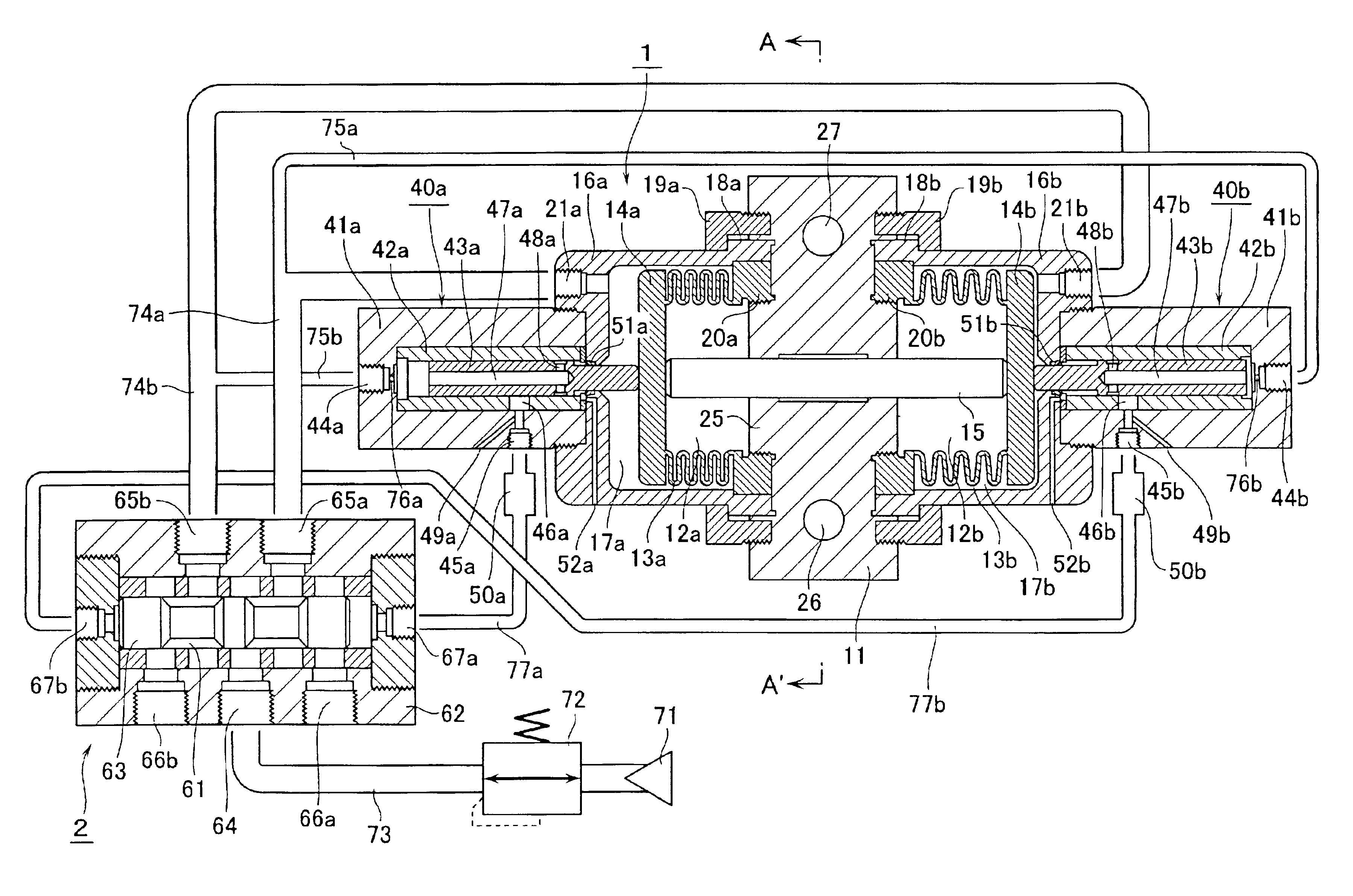
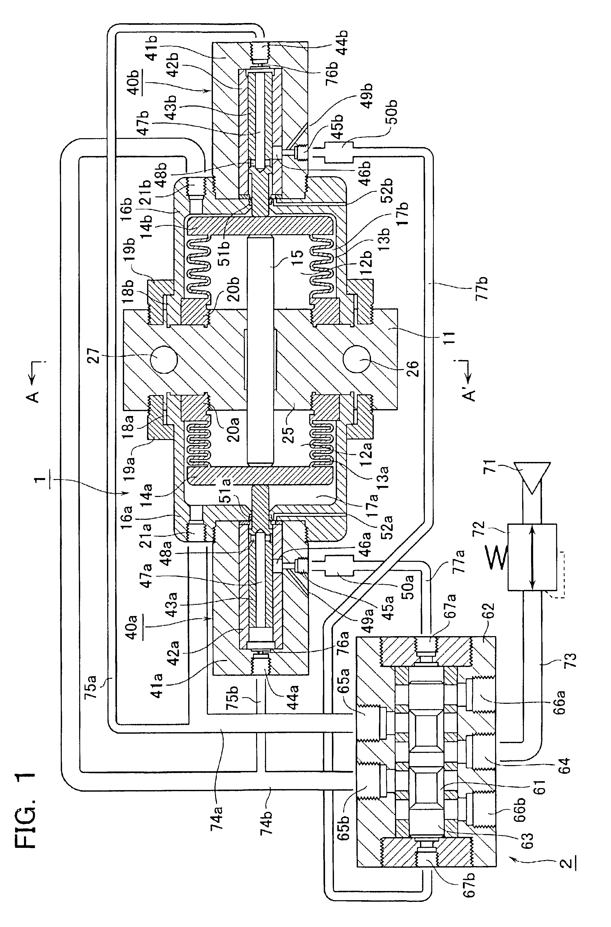
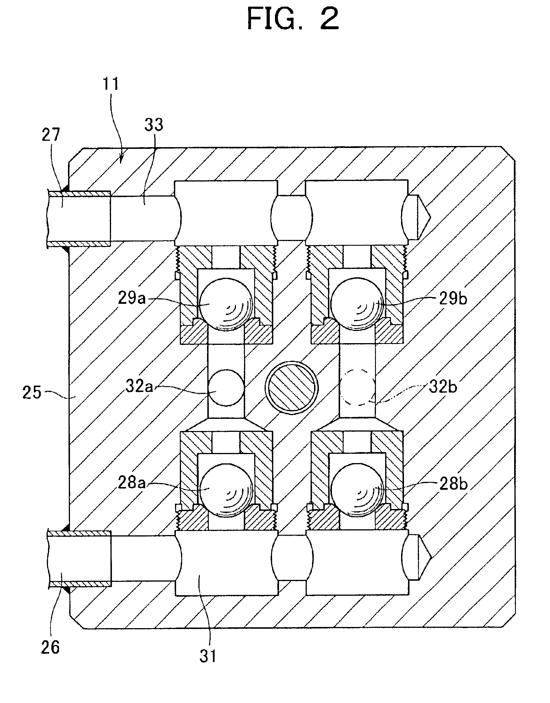
FIG. 1 is a cross-sectional view showing an arrangement of a pump system according to a first embodiment of the present invention and FIG. 2 is a cross-sectional view taken along the A-A′ line in FIG. 1.

This pump system employs switching mechanisms of a cylinder type and comprises a pump 1 and a switching valve mechanism 2 for distributing an air as an actuating fluid into the pump 1.

The pump 1 includes a pair of cylindrical bellows 13a, 13b composed of flexible members to form pump chambers 12a, 12b at both sides of a pump head 11. These bellows 13a, 13b have movable end plates 14a, 14b linked together via a shaft 15 that passes through the pump head 11. The bellows 13a, 13b are individually housed in cylindrical cases 16a, 16b located at both sides of the pump head 11 to form air chambers 17a, 17b between the inner walls of the cases 16a, 16b and the outer walls of the bellows 13a, 13b. The cases 16a, 16b have stationary ends or opened edges 18a, 18b fitted in recessed portions in...

second embodiment

FIG. 3 is a cross-sectional view showing an arrangement of a pump system according to a second embodiment of the present invention. The same reference numerals are given to the almost same parts in FIG. 3 as those in FIG. 1 to omit duplication of the detailed description on the same parts.

The pump system according to this embodiment comprises a pump 3 and a switching valve mechanism 2. Switching mechanisms 80a, 80b detachably attached to the pump 3 are different from the switching mechanisms 40a, 40b in the first embodiment. The pump system according to the first embodiment is operative to turn on one of the switching mechanisms 40a, 40b having the rods 43a, 43b pressed by the bellows 13a, 13b immediately before the end of the suction process to supply the pilot air to the switching valve mechanism 2. To the contrary, the second embodiment is operative to turn on one of the switching mechanisms 80a, 80b having rods pressing the bellows 13a, 13b from behind immediately before the end...

third embodiment

FIG. 4 is a cross-sectional view showing an arrangement of a pump system according to a third embodiment of the present invention. The same reference numerals are given to the almost same parts in FIG. 4 as those in FIG. 1 to omit duplication of the detailed description on the same parts.

The pump system according to this embodiment comprises a pump 4 and a switching valve mechanism 2. Switching mechanisms 100a, 100b detachably attached to the pump 4 are different from the switching mechanisms 40a, 40b, 80a, 80b in the first and second embodiments. In the pump system according to the first and second embodiments, the switching mechanisms 40a, 40b, 80a, 80b are of cylinder types. To the contrary, in the third embodiment, they are of types using springs.

The switching mechanisms 100a, 100b are detachably attached to the closed ends of the cases 16a, 16b. The switching mechanisms 100a, 100b include cylindrical cases 110a, 101b fixedly and detachably screwed to the cases 16a, 16b from out...


PUM


Abstract

There is provided a pump system excellent in a maintenance ability and compatibility. The pump system comprises a pump (1) for transferring a liquid by alternately supplying air to air chambers (17a, 17b) to extend and contract a pair of bellows (13a, 13b) linked to a shaft (15). It also comprises a switching valve mechanism (2) for switching the air supplied to the pump (1). Switching mechanisms (40a, 40b) are employed to switch the pilot air for controlling the switching operation of the switching valve mechanism (2). The switching mechanisms are detachably attached to cases (16a, 16b) of the pump (1) from outside.

Description

CROSS REFERENCE TO RELATED APPLICATIONThis application is based on and claims the benefit of prior Japanese Patent Application No. 2002-118247, filed on Apr. 19, 2002, the entire contents of which are incorporated herein by reference.BACKGROUND OF THE INVENTION1. Field of the InventionThe present invention relates to a pump system for transferring a target fluid via a pump camber using reciprocating flexible members such bellows and diaphragms. In particular, it relates to a pump system using a control fluid to drive a switching valve mechanism for an actuating fluid.2. Description of the Related ArtA bellows pump is known as a liquid injection pump for use in semiconductor processes and so forth in the art. It employs fluororesin bellows for sucking and discharging a liquid. The bellows pump includes a pump head containing a valve unit; a pair of bellows located at both sides of the pump head to form pump chambers inside these bellows; and a case for covering the outside of the bel...

Claims


Application Information

Patent Timeline
Patent Type & Authority Patents(United States)
IPC IPC(8): F04B9/00F04B9/135F04B43/00F04B43/06F04B43/08F04B43/10
CPCF04B9/135B05C11/10F04B17/00
Inventor WATANABE, TSUYOSHIMORISHITA, MASAOSAWADA, TSUTOMUONIDUKA, TOSHIKI
Owner IWAKI
Why Eureka
Try Eureka