Photoluminescent floor tile

Inactive Publication Date: 2005-04-05
ND HLDG
View PDF13 Cites 10 Cited by
  • Summary
  • Abstract
  • Description
  • Claims
  • Application Information

AI Technical Summary

Benefits of technology

Some of the disbursed photoluminescent material is located on the top surface of the tile. This material absorbs and discharges light to and from the tile. Photoluminescent material preferably makes up about 20 percent by weight of the combined weight of the base and photoluminescent material. This provides effective particle density on the top surface of the tile. Wear of the tile exposes fresh photoluminescent material so that the tile retains its ability to glow in the dark despite heavy use.
The tiles of the present invention are not limited to just backup lighting systems. The tiles can also be combined with conventional tile to generate interesting visual displays that appear when the lights are turned off. This enables businesses to offer customers a unique and appealing light display in addition to conventional decoration schemes.

Problems solved by technology

Often, however, electric service is lost during the emergency and the building interior goes black.
Although valuable, backup lighting has disadvantages.
Extensive coverage can be expensive to install.
Photoluminescent systems require additional labor to install them.
Often the photoluminescent tiles do not provide a pleasing appearance under normal light.

Method used


Image

  • Photoluminescent floor tile
  • Photoluminescent floor tile
  • Photoluminescent floor tile

Examples


first embodiment

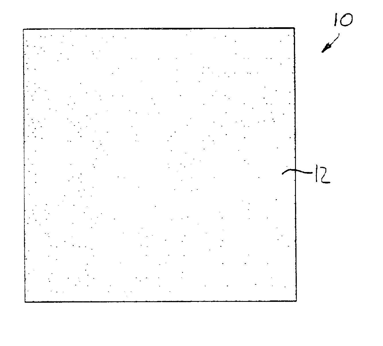
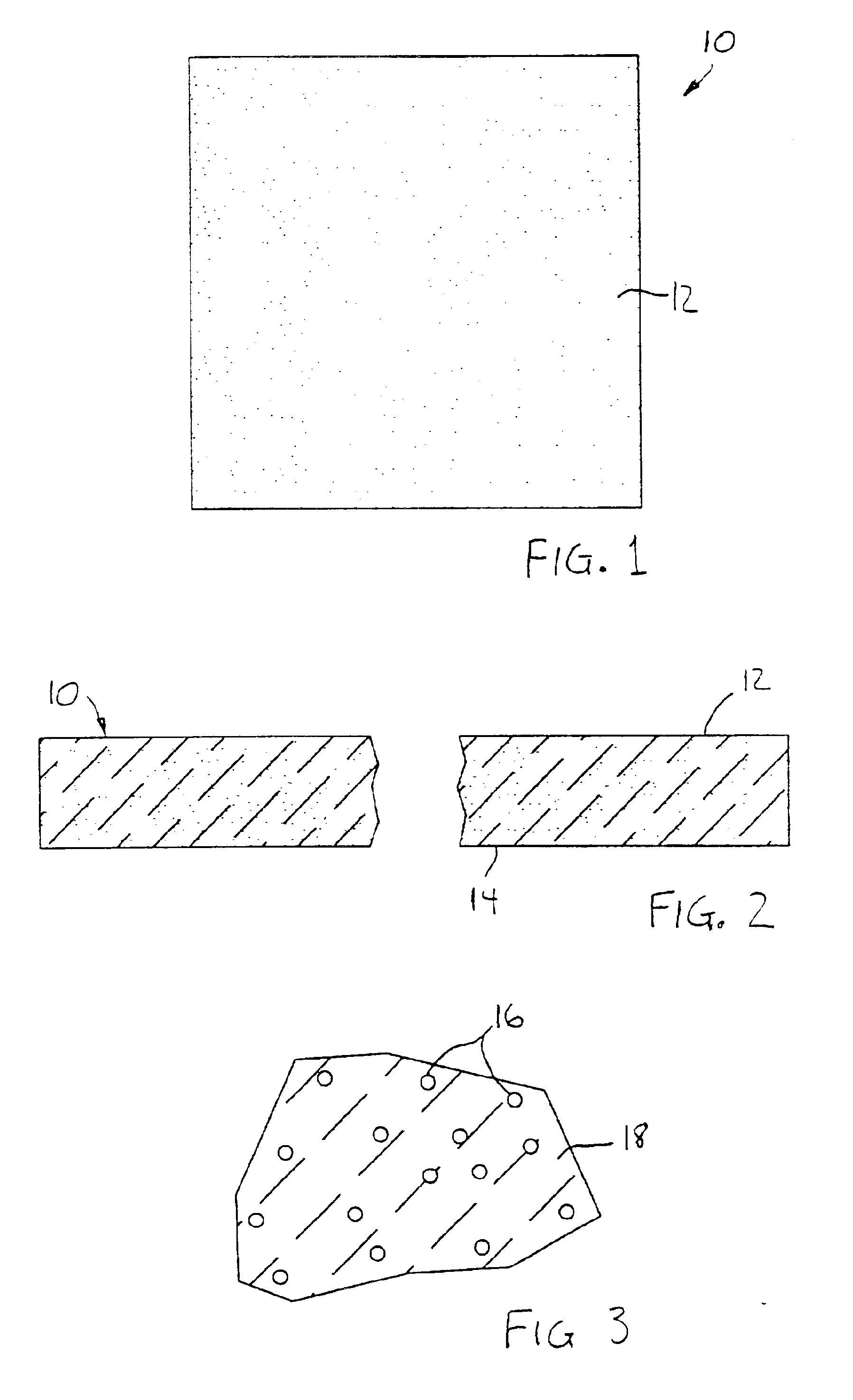
FIGS. 1-3 illustrate a first embodiment floor tile 10 in accordance with the present invention. The tile has a top surface 12 and a bottom surface 14. The illustrated tile is 12 inches by 12 inches square and approximately one-tenth of an inch thick. Other embodiments of floor tile can have different shapes or dimensions.

The tile 10 is formed from a tile composition that has photoluminescent particles 16 uniformly disbursed throughout a tile base 18 (the particles 16 are representated as black dots in FIGS. 1 and 2 and represented by circles in FIG. 3). The particles 16 are firmly embedded in the base 18 and together form a rigid floor tile.

The photoluminescent particles 16 preferably consist of a non-radioactive photoluminescent pigment. A suitable pigment is formed from rare earth materials. These photoluminescent pigments are each characterized by low toxicity, short excitation time, high brightness and long glow life. One such pigment is formed from strontium aluminate having a ...

second embodiment

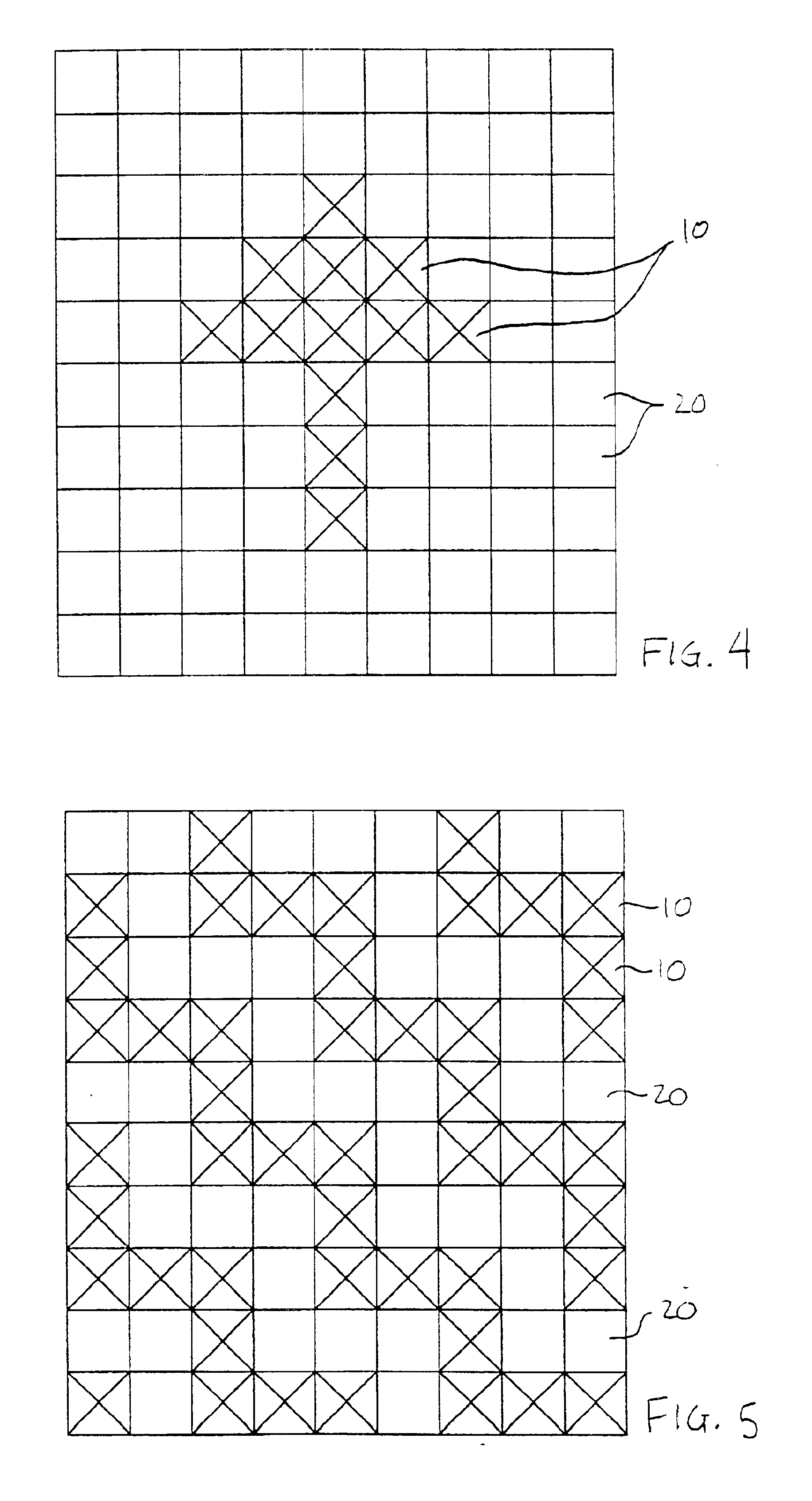
The tile 10 has photoluminescent particles distributed throughout the entire top surface of the tile to present a uniformly illuminated tile in the dark. FIG. 6 illustrates a second embodiment floor tile 110 in accordance with the present invention. The tile 110 is similar to the tile 10 but photoluminescent particles are found only in spaced-apart regions of the tile surface.

The tile 110 includes a first base 112 formed conventionally from limestone filler. The base 112 does not contain photoluminescent particles. Disbursed throughout the base 112 are a number of veins or seams 114. The veins 114 are distributed throughout the thickness of the tile 110 and are formed from a second base 116. The second base 116 is like the base 18 and includes a matrix of photoluminescent particles.

The bases 112 and 116 preferably include contrasting coloring agents to give a mottled appearance to the tile 110. The coloring agents can be the same as used in conventional mottled tile. The base 112 is...

third embodiment

FIG. 7 illustrates a third embodiment floor tile 210 in accordance with the present invention. The tile 210 includes a base 212 like the base 112 and veins 214 similar to the veins 114. The tile 210 has the same composition as the tile 110 and is made the same way except that the crushed pieces forming the veins 114 are mixed in the mixer for only 40 seconds. The resulting tile 210 has a marbled appearance, as represented by the rectangles representing the veins 214.

In other embodiments of mottled tile each of the bases may include a matrix of photoluminescent particles. Under normal lighting the tile would have a mottled appearance. In darkness the entire top surface of the tile would glow.

In other embodiments of the present invention the tile composition may be suitable for manufacturing ceramic tile. A ceramic tile composition is formed from a clay filler mixed with other ingredients, including quartz, kaolin, talc and the like. The mixture is molded into tiles and the tiles are ...


PUM

PropertyMeasurementUnit
Fractionaaaaaaaaaa
Fractionaaaaaaaaaa
Fractionaaaaaaaaaa

Abstract

A photoluminescent tile composition made of a tile base and a matrix of photoluminescent material disbursed throughout the tile base. The tile base includes a non-transparent mineral filler. The photoluminescent material located on exposed surfaces absorb and release light. The same manufacturing methods and equipment used to manufacture conventional floor tile can be used to manufacture floor tiles from the tile composition.

Description

FIELD OF THE INVENTIONThe invention relates to flooring, particularly flooring made from a nontransparent filler such as limestone or clay.BACKGROUND OF THE INVENTIONBuildings are provided with emergency signs marking exits and fire escape routes. The signs direct persons out of the building in the event of fire, natural disaster or other emergency. Often, however, electric service is lost during the emergency and the building interior goes black. Persons are unable to find the escape routes or follow them, and remain in the building.Backup lighting is often relied upon to provide illumination when electric service is lost. Backup lighting systems include batteries or emergency generators that power emergency lights. The lights are located at exits and along escape routes throughout the building.Although valuable, backup lighting has disadvantages. The backup lighting system must provide coverage of all escape routes. Extensive coverage can be expensive to install. Preventative main...

Claims


Application Information

Patent Timeline
IPC IPC(8): A62B3/00B32B27/20E04F15/08E04F15/02G09F13/20
CPCA62B3/00B32B27/20E04F15/08G09F13/20E04F15/02B32B2419/04Y10T428/16E04F2290/026
Inventor NOLT, ROBERT
Owner ND HLDG
Why Eureka
Try Eureka