Transponder identification system

a transducer and identification system technology, applied in the field of transponder identification system, can solve the problems of time-consuming above-processing, and achieve the effect of substantially reducing the time taken to identify the transducer in the overall process

Inactive Publication Date: 2005-04-05
IDENTEC
View PDF17 Cites 33 Cited by
  • Summary
  • Abstract
  • Description
  • Claims
  • Application Information

AI Technical Summary

Benefits of technology

Using this system, not all of a transponder's fields need be interrogated for that transponder to be

Problems solved by technology

However, the above process can be time consuming, particularly where th

Method used


Image

  • Transponder identification system
  • Transponder identification system
  • Transponder identification system

Examples


Embodiment Construction

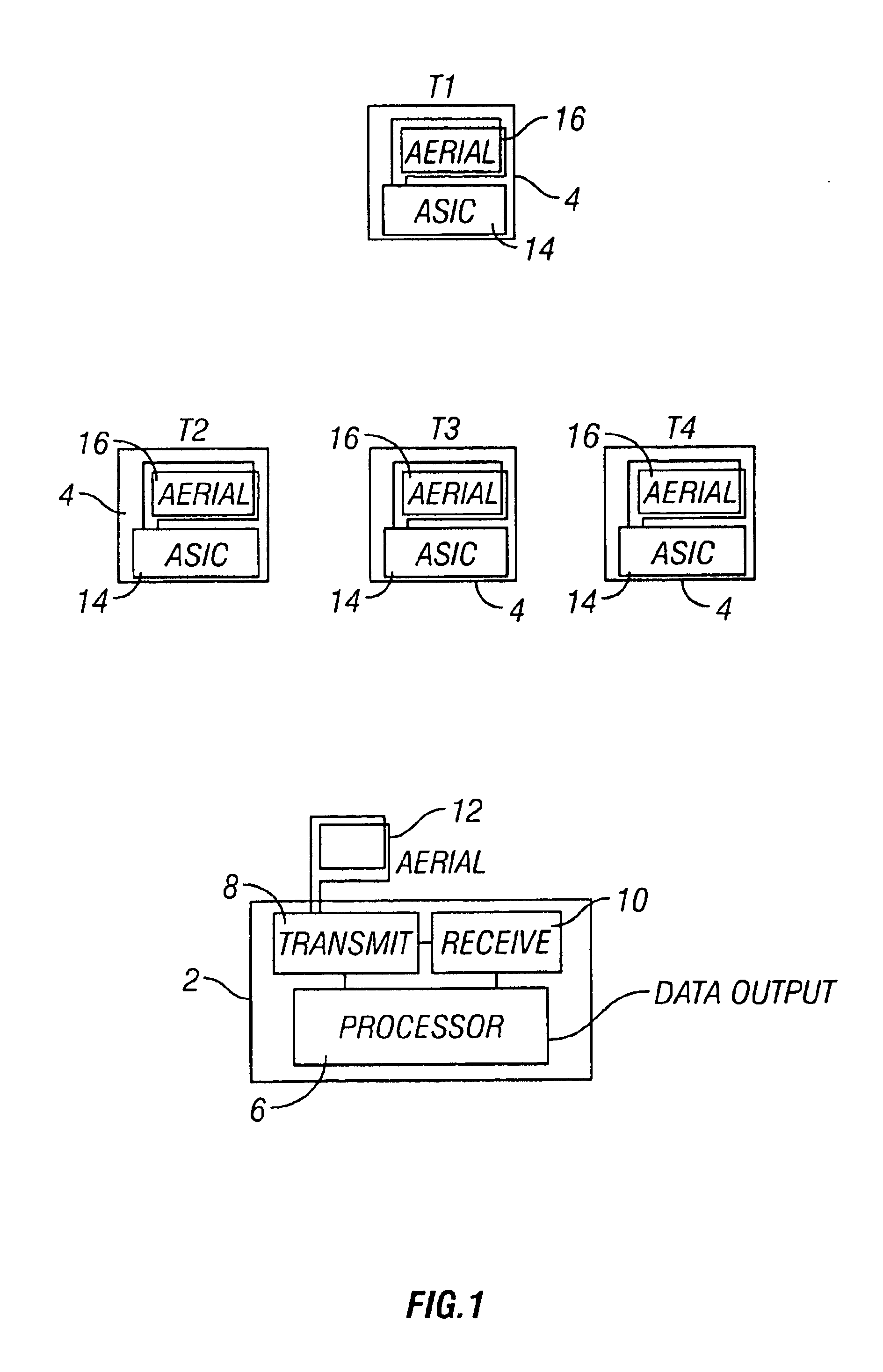
Referring to FIG. 1 of the drawings, a transponder identification system is shown comprising an interrogation device (reader) 2 and a plurality of transponders 4 (tags).

The interrogation device 2 comprises a processor 6 connected to respective means 8 and 10 for transmitting and receiving signals via an aerial 12.

Each transponder 4 comprises an application specific integrated circuit (ASIC) 14 which comprises processing means as well as means for transmitting and receiving signals via an aerial 16.

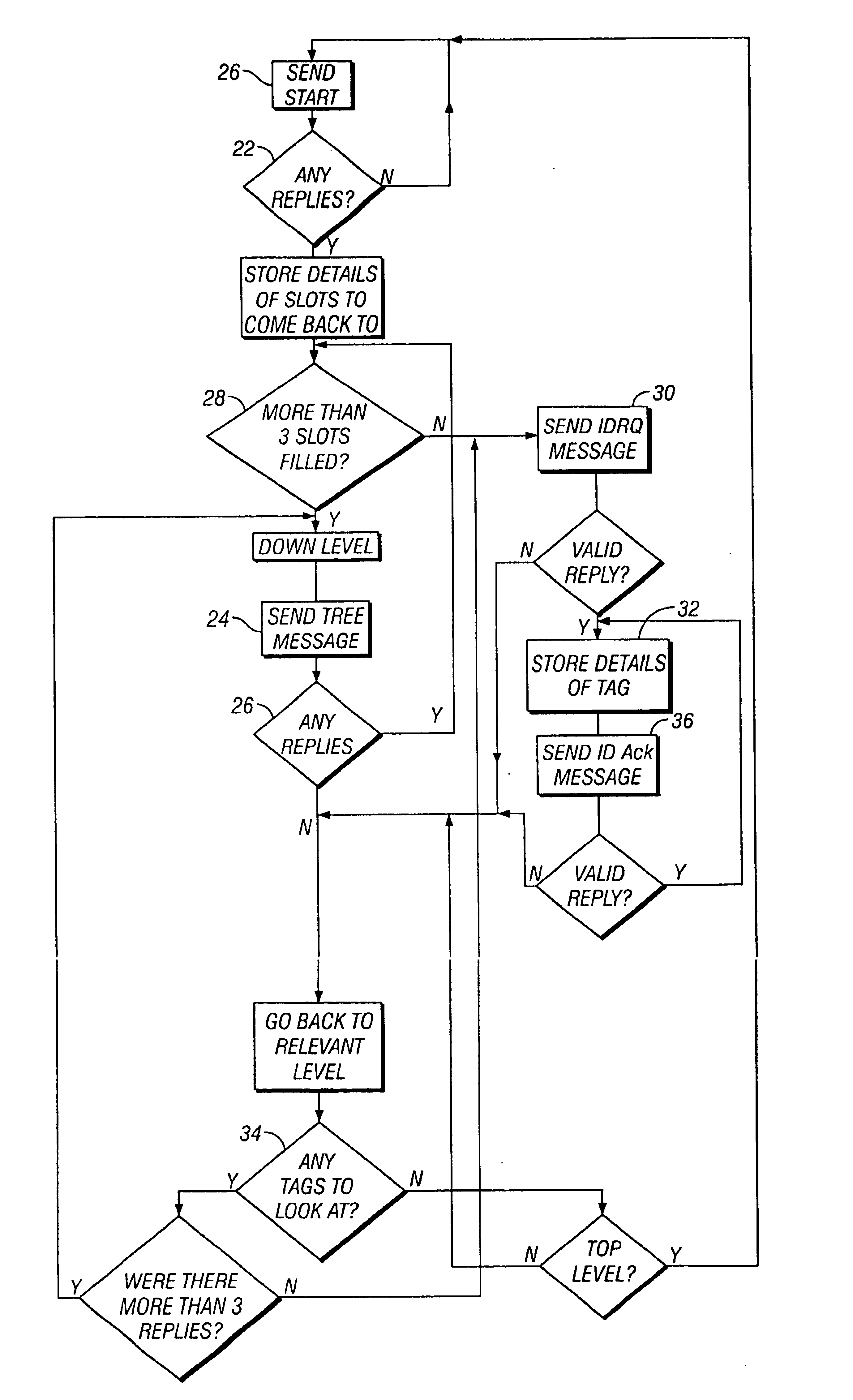
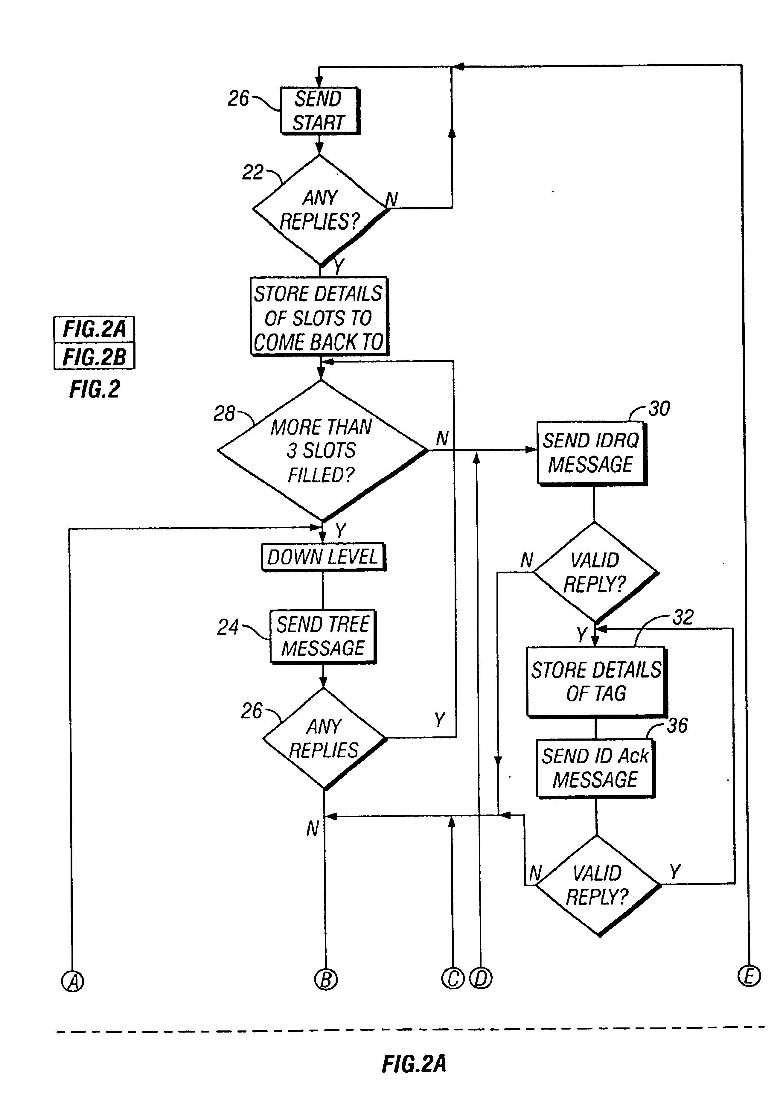
In order to identify any transponder lying within its range, the interrogation device 2 follows the sequence shown in FIG. 2 and first transmits at 20 a radio frequency initiation signal (a START message), in response to which each transponder 4, within range, will transmit at 22 a radio frequency response signal in a time slot corresponding to the value held by the transponder in a first field. For example, a transponder having the value 3 stored in its first field might transmit a respon...


PUM


Abstract

A transponder identification system comprising a plurality of transponders and an interrogation device arranged to identify each of the transponders by transmitting successive interrogation signals according to a systematic search strategy, wherein the search is truncated where the interrogation device receives fewer than a predetermined number of different responses from the transponders, to a transmitted interrogation signal.

Description

FIELD OF THE INVENTIONThe present invention relates to a transponder identification system.BACKGROUND OF THE INVENTIONVarious systems are known in which an interrogation device (reader) can determine the respective identities of two or more transponders (tags) lying within its detection field.GB-2202981 and U.S. Pat. No. 5,339,703 describe one known type of identification system which uses a “tree and branch” search methodology to identify transponders. Each transponder has stored therein a unique identity code comprising a plurality of fields, each field holding a respective value selected from a plurality of possible values. Each value is typically represented as a short binary code.The system identifies transponders by first transmitting a radio frequency initiation signal, in response to which each transponder, within range, will transmit a radio frequency response signal in a time slot corresponding to the value held by the transponder in a first field. For example, a transpond...

Claims


Application Information

Patent Timeline
IPC IPC(8): G07C9/00G06K7/00
CPCG06K7/0008G07C9/00111G06K7/10049G07C2209/08G07C9/28
Inventor REGAN, BERNARD JOHN
Owner IDENTEC
Why Eureka
Try Eureka