Disk drive including an airflow diverter element radially between spindle motor axis of rotation and cavity in shroud surface

Inactive Publication Date: 2005-04-05
WESTERN DIGITAL TECH INC
View PDF10 Cites 81 Cited by
  • Summary
  • Abstract
  • Description
  • Claims
  • Application Information

AI Technical Summary

Benefits of technology

[0011]According to various embodiments, the airflow diverter element may be formed of plastic, and may be adhesively attached to the cover. The disk drive may further include a disk clamp for engaging the disk to the spindle motor. The disk clamp may have a top surface disposed toward the cover and the airflow diverter element may extend toward the disk surface at least to the top surface of the disk clamp. The airflow diverter element may extend toward the disk surface beyond the top surface of the disk clamp. The airflow diverter element may be triangular shaped. The airflow diverter element may be tapered from a larger

Problems solved by technology

Rotation of the hub results in the rotation of the attached disks.
Such airflow adjacent the top of the spindle motor, however, may have certain undesirable effects.
However, t

Method used


Image

  • Disk drive including an airflow diverter element radially between spindle motor axis of rotation and cavity in shroud surface
  • Disk drive including an airflow diverter element radially between spindle motor axis of rotation and cavity in shroud surface
  • Disk drive including an airflow diverter element radially between spindle motor axis of rotation and cavity in shroud surface

Examples


Embodiment Construction

[0016]Referring now to the drawings wherein the showings are for purposes of illustrating preferred embodiments of the present invention only, and not for purposes of limiting the same, FIGS. 1-4 illustrate a disk drive including an airflow diverter element in accordance with the aspects of the present invention.

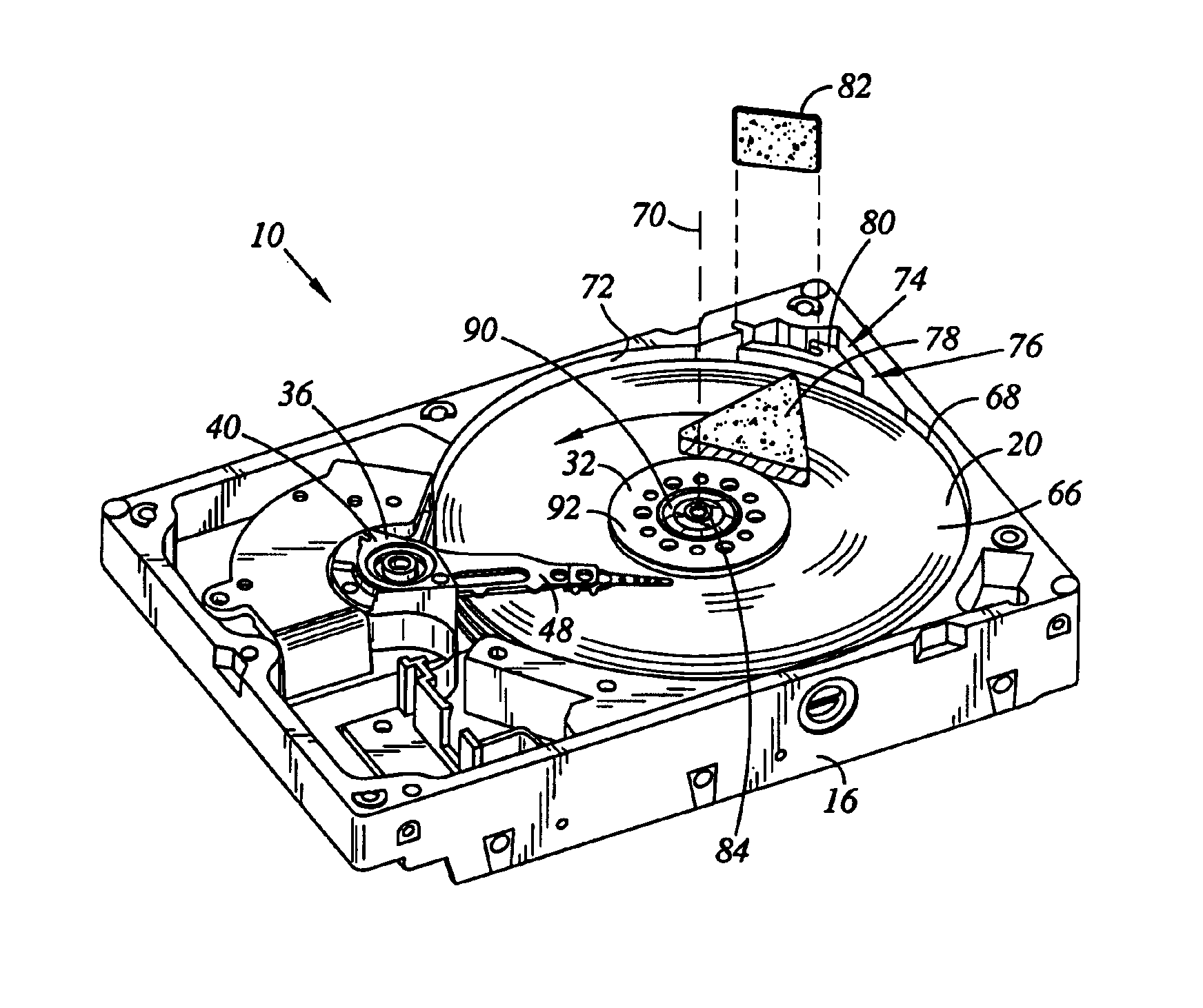
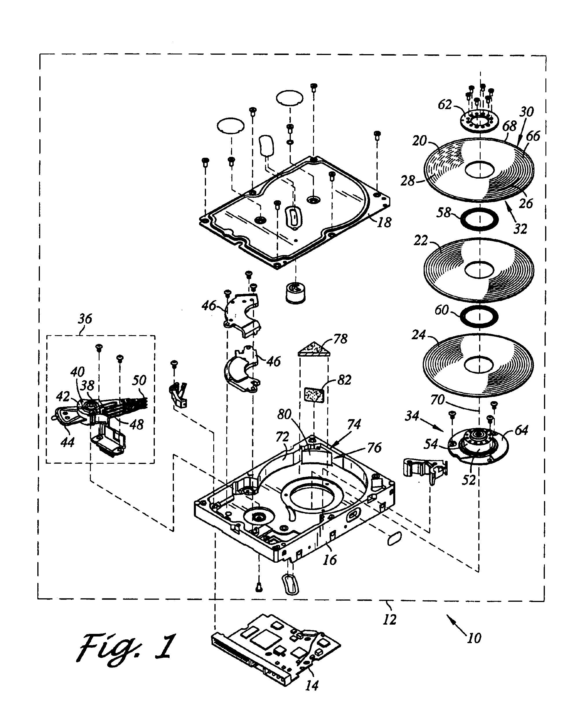
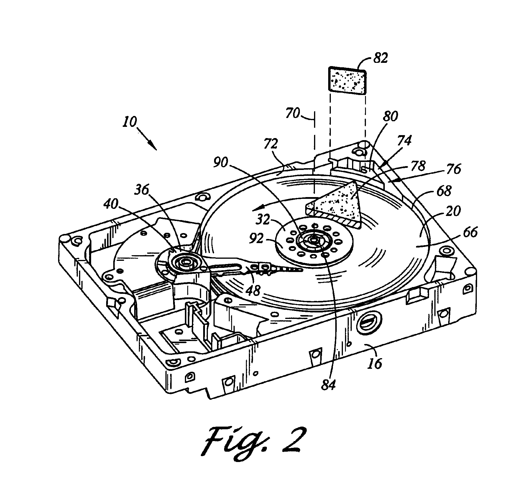
[0017]Referring now to FIG. 1 there is depicted an exploded perspective view of a disk drive 10 constructed in accordance with an aspect of the present invention. In the embodiment shown, the disk drive 10 includes a head disk assembly (HDA) 12 and a printed circuit board assembly (PCBA) 14. The head disk assembly 12 includes a housing, which may include a disk drive base 16 and a cover 18 that collectively house magnetic disks 20, 22, 24. Each magnetic disk 20, 22, 24 contains a plurality of tracks for storing data. The magnetic disks 20, 22, 24 may be two-sided, and thus for example, the magnetic disk 20 is shown having a track 26 on an upper facing side 30 and a track 28 ...


PUM


Abstract

A disk drive including a disk drive base and a cover attached to the disk drive base. The disk drive further includes a rotatable disk including a disk surface extending to an outer periphery. The disk drive further includes a spindle motor including an axis of rotation. The spindle motor is rotatably coupled to the disk drive base for rotating the disk about the axis of rotation. The disk drive further includes a shroud surface concentrically formed about and adjacent the outer periphery. The disk drive further includes a cavity formed in the shroud surface. The cavity extends to a cavity opening adjacent the outer periphery. The disk drive further includes an airflow diverter element extending from the cover towards the disk surface radially between the cavity opening and the axis of rotation for diverting disk rotation induced airflow adjacent the disk surface.

Description

BACKGROUND OF THE INVENTIONCROSS-REFERENCE TO RELATED APPLICATIONS[0002]Not applicable.[0003]1. Field of the Invention[0004]The present invention relates generally to disk drives, and in particular to a disk drive including an airflow diverter element radially between a spindle motor axis of rotation and a cavity in a shroud surface.[0005]2. Description of the Prior Art[0006]The typical hard disk drive includes a disk drive base, and a head disk assembly (HDA) and a printed circuit board assembly (PCBA) attached to the disk drive base. The head disk assembly includes at least one magnetic disk, a spindle motor for rotating the disk, and a head stack assembly (HSA) that includes at least one transducer head, typically several, for reading and writing data from and to the disk. The printed circuit board assembly includes a servo control system in the form of a disk controller for generating servo control signals. The head stack assembly is controllably positioned in response to the ge...

Claims


Application Information

Patent Timeline
IPC IPC(8): G11B5/60G11B25/04G11B33/14
CPCG11B5/6005G11B25/043G11B33/142
Inventor LITTLE, AARON D.
Owner WESTERN DIGITAL TECH INC
Why Eureka
Try Eureka