System for precision miter cutting

a technology of precision miter cutting and miter saw, which is applied in the field of system for miter cutting, can solve the problems of inability to use the demarco angle-modeling device on the miter saw, increased processing difficulty, and inability to accurately model the angle of the miter saw, and achieve the effect of facilitating the cutting of workpieces

Inactive Publication Date: 2005-04-12
KANAGA LAWRENCE W
View PDF12 Cites 21 Cited by
  • Summary
  • Abstract
  • Description
  • Claims
  • Application Information

AI Technical Summary

Benefits of technology

The present invention solves the problems of the prior art by, among other things, providing a device for modeling an angle formed by two convergent surfaces and a system for transferring one half of that modeled angle directly to a miter saw to facilitate the cutting of workpieces to border the convergent surfaces, which can be manufactured with or retrofitted onto a standard power miter saw and can also be used with a hand miter saw which is designed to accommodate it.

Problems solved by technology

However, the process becomes more difficult if the convergence angle does not correspond to an angle having a preset cutting position on the miter saw.
Moreover, most moldings or trim are not of equidimensional design, in that they have a planar surface which opposes an ornamental surface and top and bottom edges which may differ in width.
The primary problems associated with using such devices are that they are prone to inaccuracies, because, among other things, they involve one or more intermediate steps between the measurement of the existing angle and the setting of the miter saw, each of which is capable of introducing error.
The Demarco miter saw, as described in the '821 patent, deviates from standard power miter saws so much that it would be impossible to use the DeMarco angle-modeling device on miter saws which have not been specifically manufactured in accordance therewith.
DeMarco does not demonstrate flaws in the standard power miter saw design or provide justification for changing manufacturing practices to produce miter saws as those shown in the '821 patent, and his design introduces a variety of problems not presented by the standard design.
This configuration decreases support for the workpiece and increases the possibility that it will move during the cutting process, thereby compromising accuracy, since the cutting action of the blade tends to move or bend the workpiece.
The configuration also reduces the operator's options with regard to stabilizing the workpiece against the fence, thus creating safety issues which are not found in the standard design.
Another problem with the DeMarco design relates to the need to move the fences to duplicate the angel of convergence.
This configuration increases the complexity and difficulty associated with using the DeMarco miter saw because it requires the reorientation of the workpiece, and any workpiece support system, for different angles and for mitering separate pieces to frame the same angle.
The DeMarco miter saw presents further difficulty in using it to frame an interior angle because each fence blocks the path of a workpiece placed against the other, thus eliminating the operators ability to make one cut for both dimension and angle.

Method used


Image

  • System for precision miter cutting
  • System for precision miter cutting
  • System for precision miter cutting

Examples


Embodiment Construction

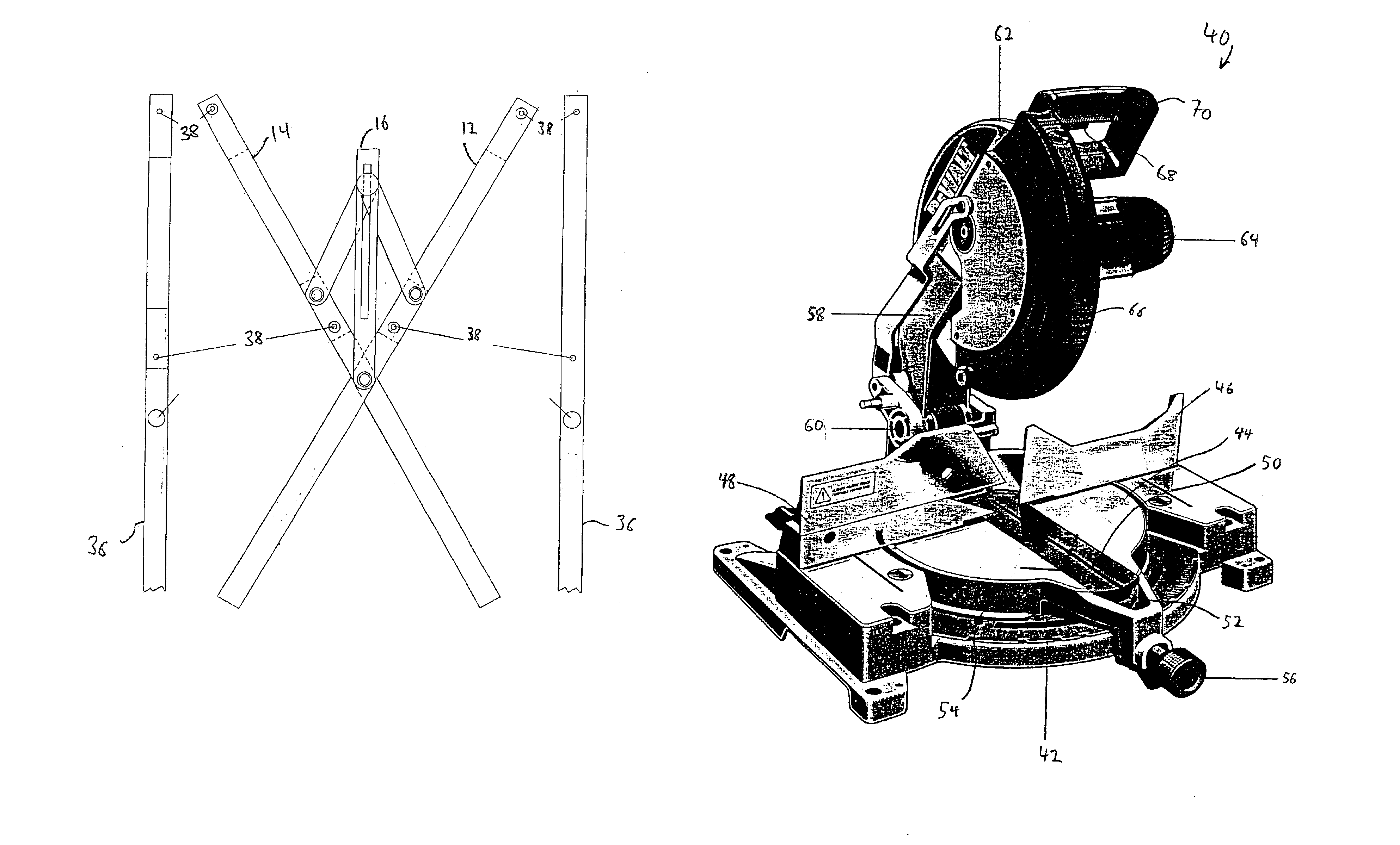
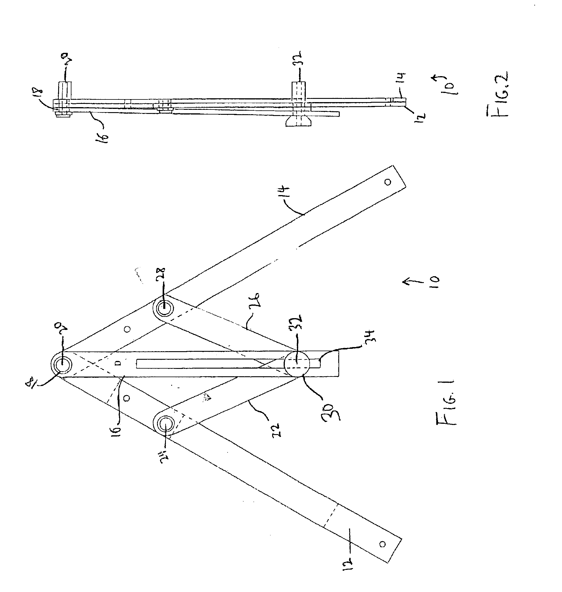
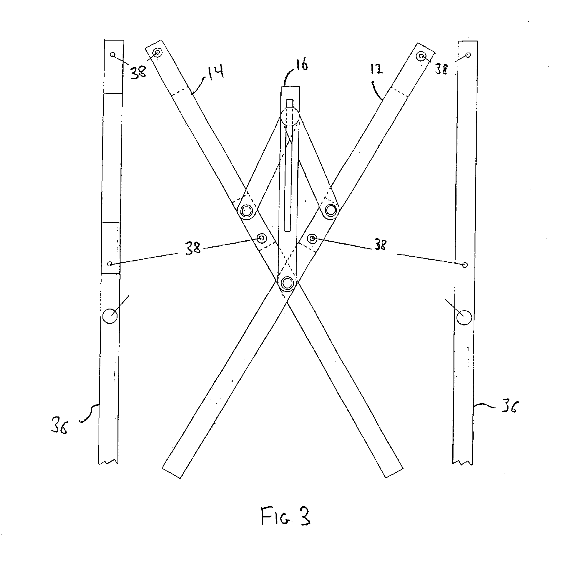
The advantages of a system for perfecting miter cuts constructed or retrofitted on a miter saw in accordance with the present invention will become more readily apparent to those having ordinary skill in the art from the following detailed description of certain preferred embodiments taken in conjunction with the drawings which set forth representative embodiments thereof. Unless otherwise apparent, or stated, directional references, such as “right,”“left,”“upper,”“below,”“horizontal”“vertical,”“upward” and “downward”, are intended to be relative to the orientation of a particular embodiment of the invention as shown in the first numbered view of that embodiment. In addition, a given reference numeral indicates the same or similar structure when it appears in different figures and like reference numerals identify similar structural elements and / or features of the subject invention.

Referring now to FIG. 1, in which there is illustrated a preferred embodiment of a miter angle modeling...


PUM

PropertyMeasurementUnit
convergence angleaaaaaaaaaa
combination angleaaaaaaaaaa

Abstract

A system for modeling a recessed or protruding angle formed by convergent surfaces and transferring that modeled angle directly to a miter saw for facilitating the cutting of workpieces in conformance with the bisection of that modeled angle. This system may be manufactured with, or retrofitted onto a standard miter saw or used with a hand miter saw designed to accommodate the system.

Description

BACKGROUND OF THE INVENTION1. Field of the InventionThe present invention relates to a system for miter cutting, and more particularly, to a system for miter cutting that includes a device for modeling the angle of convergent surfaces and transposing the modeled angle to a miter saw for miter cutting through a slot defined on the miter saw.2. Background of the Related ArtThe primary function of a miter saw is to cut a piece of material (hereinafter also referred to as a “workpiece”) at a defined angle. Miter saws are most often used to prepare moldings or decorative trim to fit adjacent to surfaces that converge to form an angle, such as an inside or outside corner, so that the moldings or trim appear to follow along the surfaces continuously.For practical reasons as well as aesthetics, the workpieces are fit to the convergent surfaces by cutting each of the workpieces at an angle which equals, as nearly as possible, one half of the angle formed at the convergence.Most, if not all, ...

Claims


Application Information

Patent Timeline
Patent Type & Authority Patents(United States)
IPC IPC(8): B43L7/00B43L7/10B23D59/00B27G5/02E04F21/00
CPCB23D59/002E04F21/0076E04F21/0069B27G5/02
Inventor KANAGA, LAWRENCE W.
Owner KANAGA LAWRENCE W
Why Eureka
Try Eureka