
Illuminated caliper instrument

Inactive Publication Date: 2005-04-12
MACKIN ROBERT A +1
View PDF19 Cites 8 Cited by
  • Summary
  • Abstract
  • Description
  • Claims
  • Application Information

AI Technical Summary

Benefits of technology

Accordingly, it is an object of the invention to provide a caliper instrument which provides adequate illumination to a person working under night conditions for very low ambient illumination conditions for utilization of a caliper instrument to measure or delineate the distance between points on a document or object without impairing the night vision of the person measuring coordinating the distance between the points.

Problems solved by technology

Although a need for solving this problem has existed for long time, no practical means for solving the problem, such as a compact, reasonably inexpensive illuminated caliper instrument, has been provided.

Method used


Image

  • Illuminated caliper instrument
  • Illuminated caliper instrument
  • Illuminated caliper instrument

Examples


Embodiment Construction

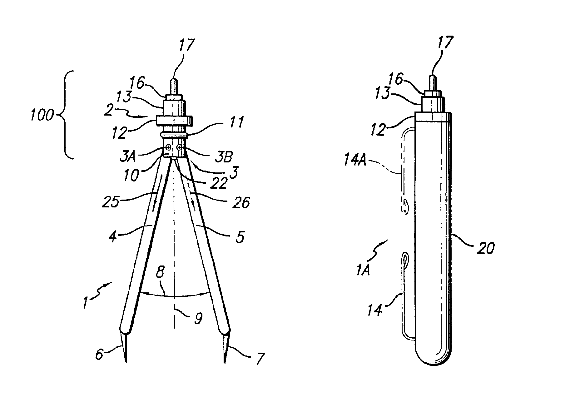
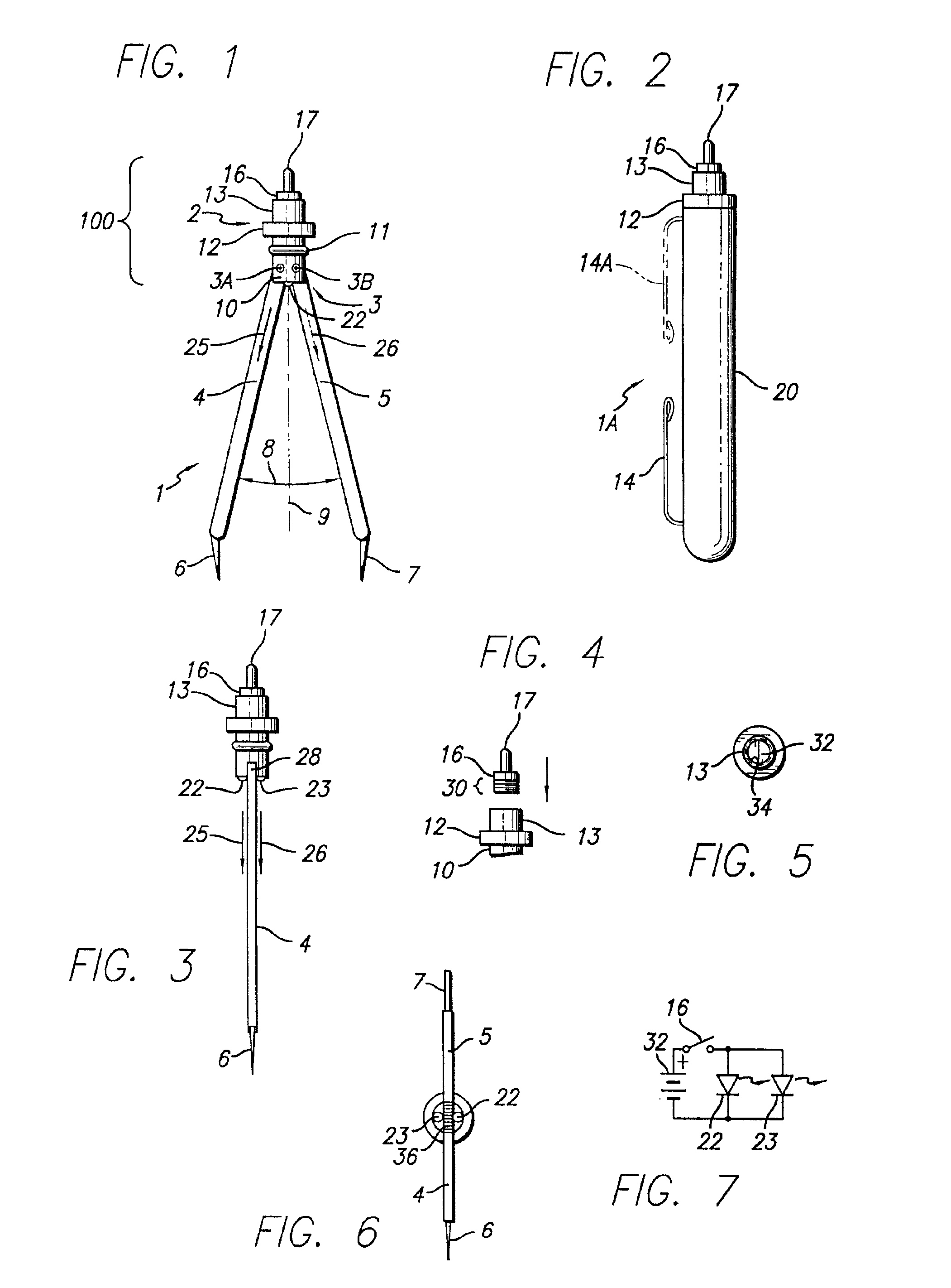
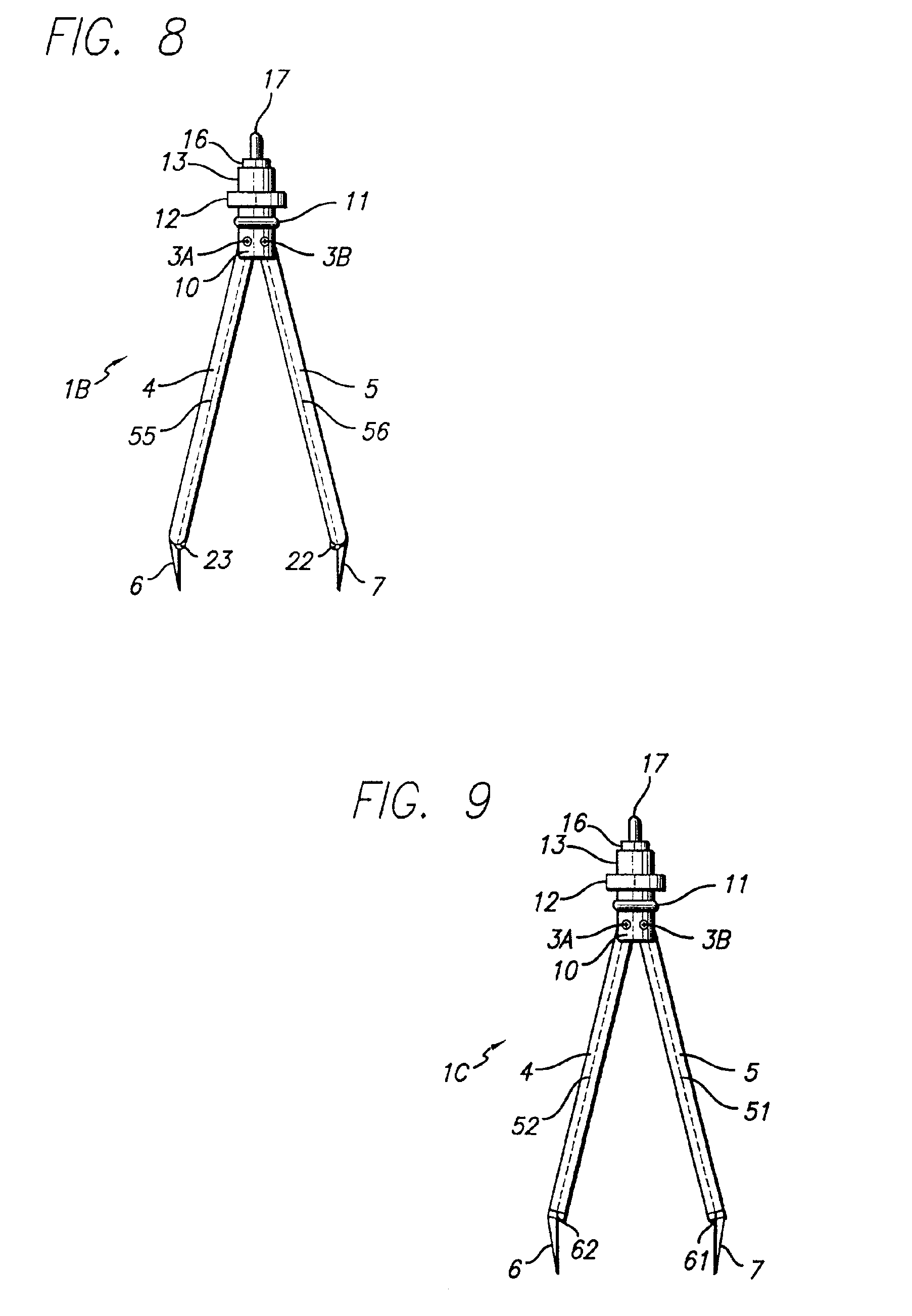
Referring to FIG. 1, illuminated caliper instrument 1 includes a hub 100 from which a pair of caliper legs 4 and 5 downwardly extend. Hub 100 includes an upper section 2 and a lower section 3. A pair of needles 6 and 7 extend downwardly from the lower ends of legs 4 and 5, respectively. Legs 4 and 5 are attached to a gear mechanism 36 in lower section 3 (see the bottom view shown in FIG. 6) which can be essentially identical to that disclosed in the above referenced U.S. Pat. No. 5,115,571, so that when the caliper legs 4 and 5 are pivoted about pivot ends 3A and 3B so that caliper legs 4 and 5 are “opened” or “closed” as indicated by are 8, the movement of each leg 4 and 5 is symmetrically opposite with reference to a bisection axis 9. (Alternatively, the upper ends of legs 4 and 5 can be pivotally attached to hub 100 without use of gear mechanism 36.)

Lower section 3 includes the above-mentioned gear mechanism 36, which includes two engaged gears attached to the upper ends 28 of ca...


PUM


Abstract

An illuminated caliper device includes a caliper assembly having first and second caliper legs each having a pointed tip and a pivot end. A pivot support and first and second pivot elements pivotally connects the pivot ends of the first and second caliper legs to the pivot support. A battery housing attached to the pivot support contains a battery. First and second light emitting diodes are coupled by a switch mounted on the battery housing to first and second terminals of the battery and produced light that is directed to areas of the surface to be measured by pointed tips of the legs. The intensity and color of light emitted by the first light emitting diode are such as to sufficiently illuminate the surface under low ambient illumination conditions without disrupting acquired night vision of a user.

Description

BACKGROUND OF THE INVENTIONThe invention relates to calipers or caliper instruments (also sometimes referred to as dividers) of the type utilized by persons who work in dark environments, for example paramedics needing to make measurements on a medical chart plotted by a heart monitoring instrument under “field conditions”, navigators, aviators, and other persons who must measure the distance between two points of a chart plotted by an instrument, a map, or other document under very low ambient illumination conditions. It is important that the “night vision” of such persons not be temporarily disrupted by the presence of unnecessarily bright “white” light on the document (or other surface) to allow measurement of the distance between two points on the document. A person whose eyes are open for approximately 15 to 20 minutes under dark conditions or very low ambient illumination conditions acquires what is known as “night vision”, wherein the person's eyes become much more sensitive ...

Claims


Application Information

Patent Timeline
IPC IPC(8): G01B3/16
CPCG01B3/16
Inventor MACKIN, ROBERT A.MACKIN, JEFFREY M.
Owner MACKIN ROBERT A
Learn More