Iron skirt

a technology of skirts and irons, applied in the field of skirts of irons, can solve the problems of further development of shaping, high cost of expensive tools, and inability to provide a family of similar products easily

Inactive Publication Date: 2005-04-12
ROWENTA WERKE GMBH
View PDF22 Cites 0 Cited by
  • Summary
  • Abstract
  • Description
  • Claims
  • Application Information

AI Technical Summary

Benefits of technology

The object of the invention described hereinbelow is to provide an iron skirt which can be produced in a cost-effective, c

Problems solved by technology

The provision of each new type of iron skirt thus involves high costs for expensive tools, which constitutes an obstacle to the further development o

Method used


Image

  • Iron skirt
  • Iron skirt
  • Iron skirt

Examples


Embodiment Construction

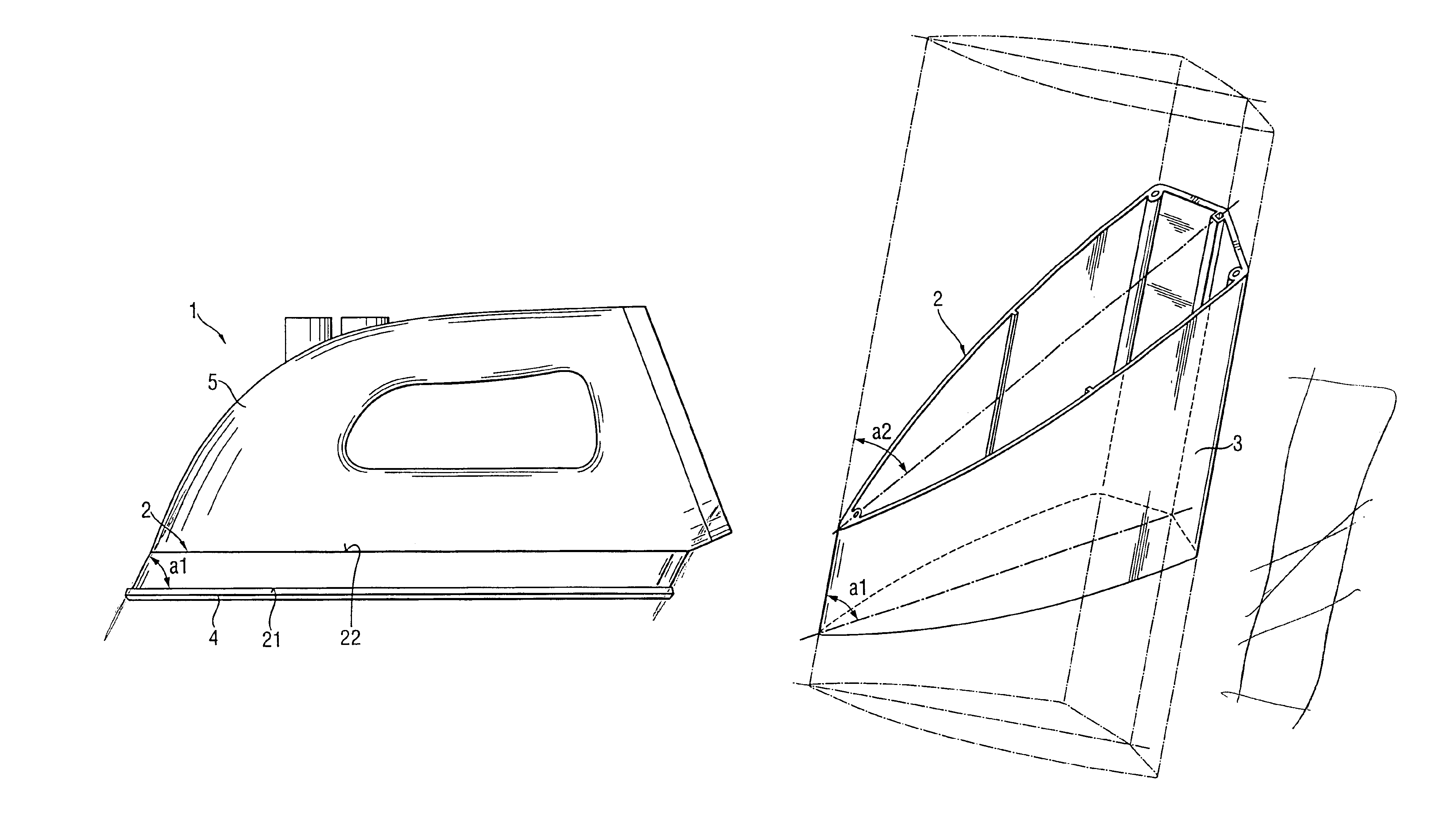
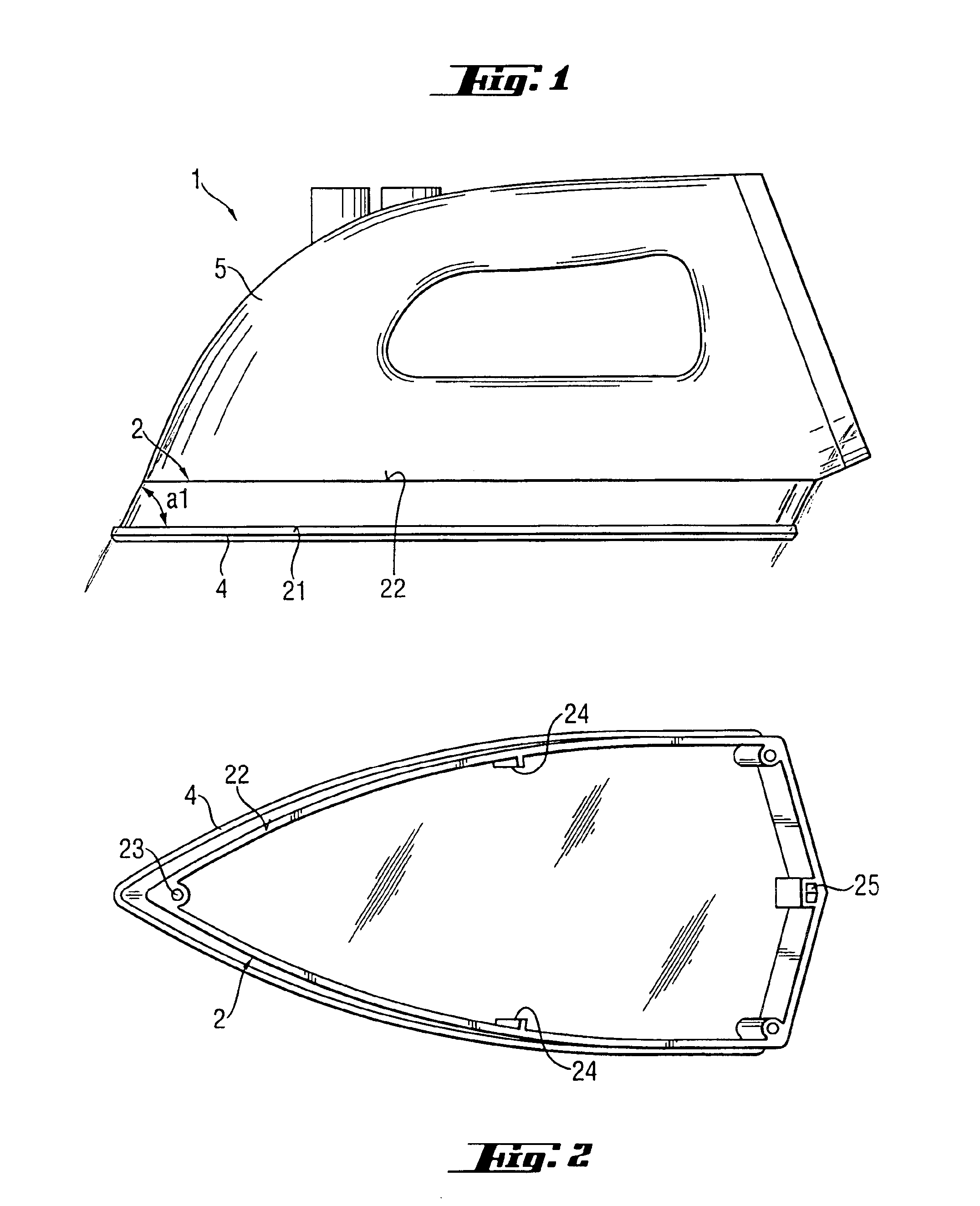
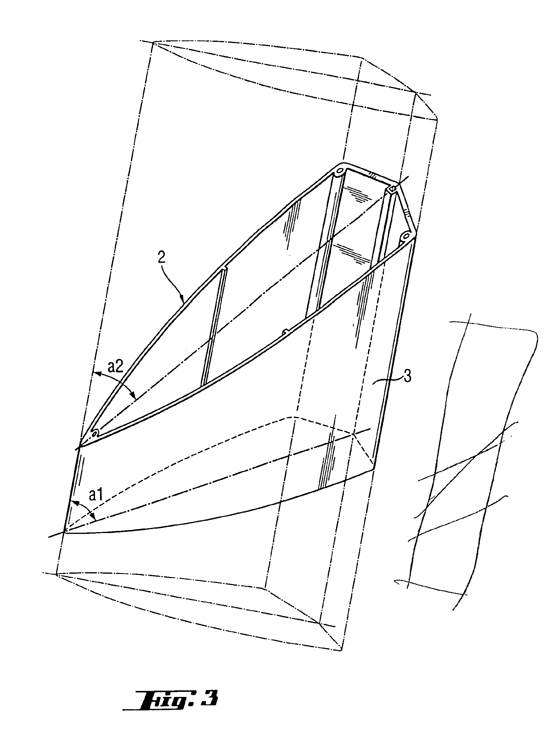
According to a preferred embodiment (FIGS. 1 and 2), the skirt 2 of an iron 1 is cut off rectilinearly from a hollow profile 3 (FIG. 3) and thus comprises a blank with parallel edges 21, 22. The cutting plane is aligned perpendicularly to the plane of symmetry of the profile and forms an angle a1 with the longitudinal axis of the profile. The skirt is connected, on the one hand, to the soleplate 4, on which it is supported by means of the cut edge 21, and, on the other hand, to the iron body 5, which it bears by means of the cut edge 22. The iron body 5 and the iron soleplate 4 are screwed securely to the iron skirt 2 by means of screws, the screws passing through through-passages 23 arranged in the profile. Ribs 24 bear a heat shield which comprises a flat metal sheet and is arranged between the skirt edge 22 and the iron body 5. Protrusions of the iron body 5 and of the iron soleplate 4 engage in channel-like recesses 25 for preliminary-centering purposes.

According to another embo...


PUM


Abstract

An iron skirt formed by a blank cut off from a hollow profile.

Description

BACKGROUND OF THE INVENTION1. Field of the InventionThe invention relates to skirts of irons.2. Discussion of the Prior ArtThe term iron skirt is intended to mean the outer visible part of the iron casing which is located directly above the hot iron soleplate. A heat shield is often installed in the iron skirt, which is usually produced from plastic, and, in the case of steam irons, is arranged between the soleplate and the water container. The iron skirt is part of the iron housing.The iron skirt has to withstand the heat of the iron soleplate and has to have certain esthetic features which are important to the user. The iron skirt is usually produced from plastic by injection molding, it being necessary for the plastic and the coloring thereof to be heat-stable. Iron skirts made of metal are usually produced, starting from a metal blank, by deep-drawing and are then provided with an esthetically pleasing protective covering, e.g. made of chrome.U.S. Pat. No. 5,613,310 discloses a ...

Claims


Application Information

Patent Timeline
IPC IPC(8): D06F75/36D06F75/00
CPCD06F75/36
Inventor STUTZER, FRANZ ALBAN
Owner ROWENTA WERKE GMBH
Why Eureka
Try Eureka