Method and dispenser for mixing and discharging media

a technology of media and dispenser, which is applied in the field of methods and dispensers to achieve the effects of improving the mixing process, simplifying the guidance of media, and easy miscibility of media

Inactive Publication Date: 2005-04-12
APTAR RADOLFZELL
View PDF18 Cites 52 Cited by
  • Summary
  • Abstract
  • Description
  • Claims
  • Application Information

AI Technical Summary

Benefits of technology

An object of the invention is to provide a method and dispenser simplifying the guidance of the media, which reduces the requirement for easy miscibility of the media and which improves the mixing process.
Advantageously, the second chamber (medium reservoir) can at least be zonally deformable. As a result even in the case of changing external pressures, there is scarcely a pressure difference between atmosphere and the interior of, in particular, the second chamber, which keeps limited the fusion and gas exchange with the atmosphere. As a result, the material thicknesses of the medium reservoir wall can be kept small.

Problems solved by technology

Many pharmaceutical substances, which usually form the second medium, are not stable in the liquid or pulverulent administration form, so that they can only be mixed or dissolved just prior to administration.

Method used


Image

  • Method and dispenser for mixing and discharging media
  • Method and dispenser for mixing and discharging media
  • Method and dispenser for mixing and discharging media

Examples


Embodiment Construction

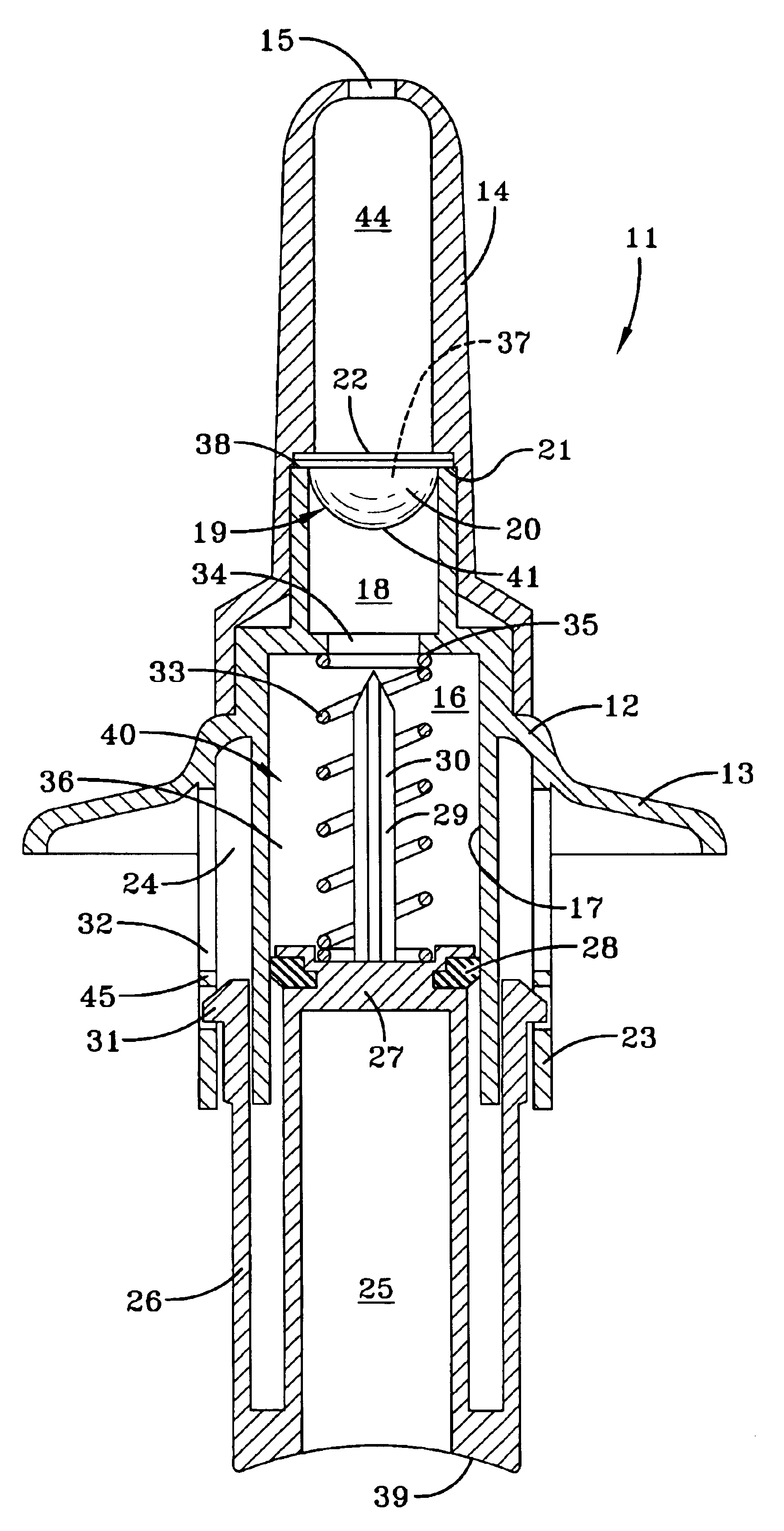
FIG. 1 shows a dispenser 11 with a base body 12, which has laterally projecting shoulders 13 on which are placed two fingers of a user. Onto the base body 12 can be engaged or screwed an elongated adaptor 14, also known as a nose olive and which has at its rounded end a discharge opening 15. The latter is shown as a relatively large, open hole, but when constructing the dispenser as an atomizer, it can also contain an atomizing nozzle.

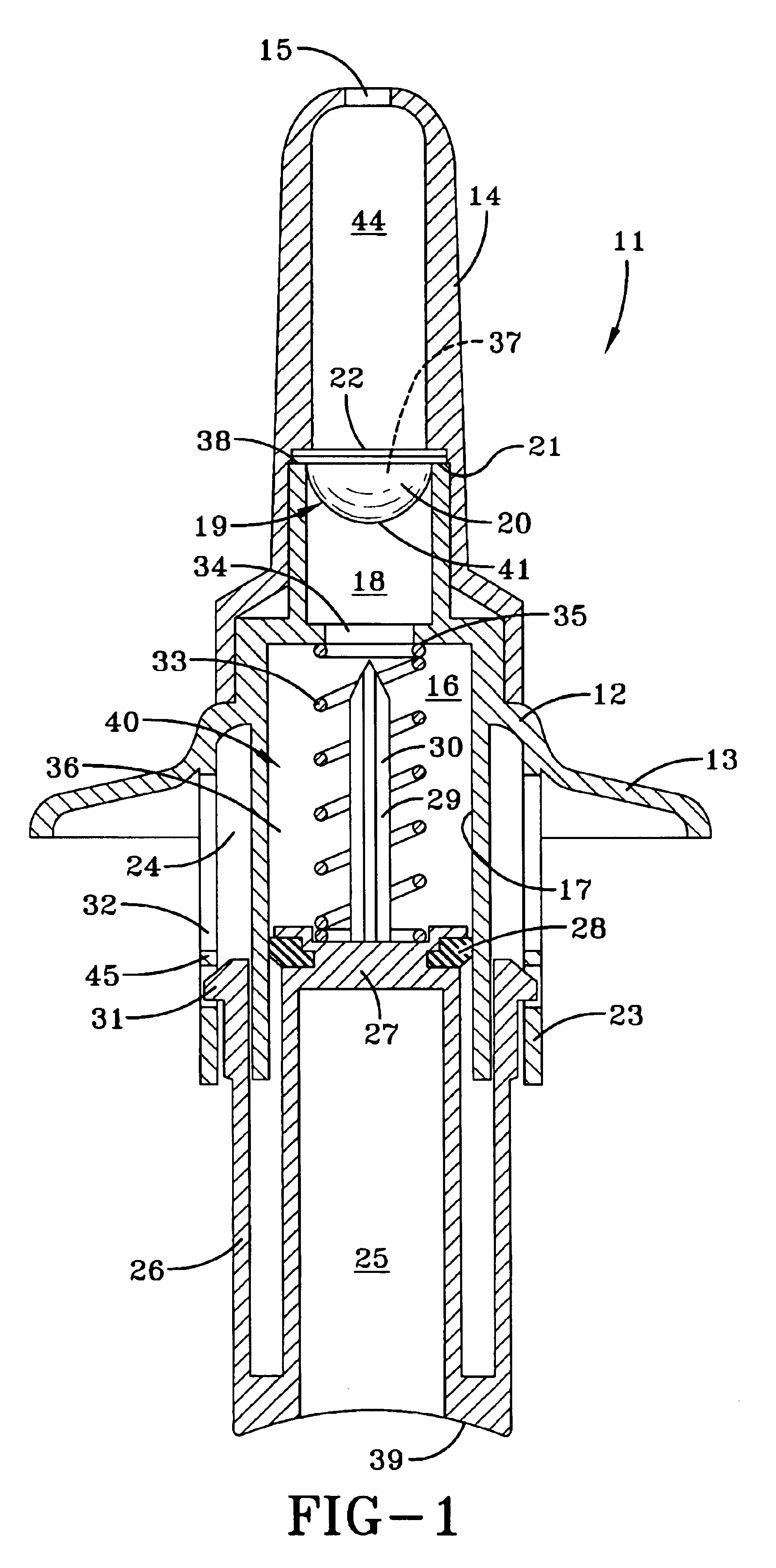
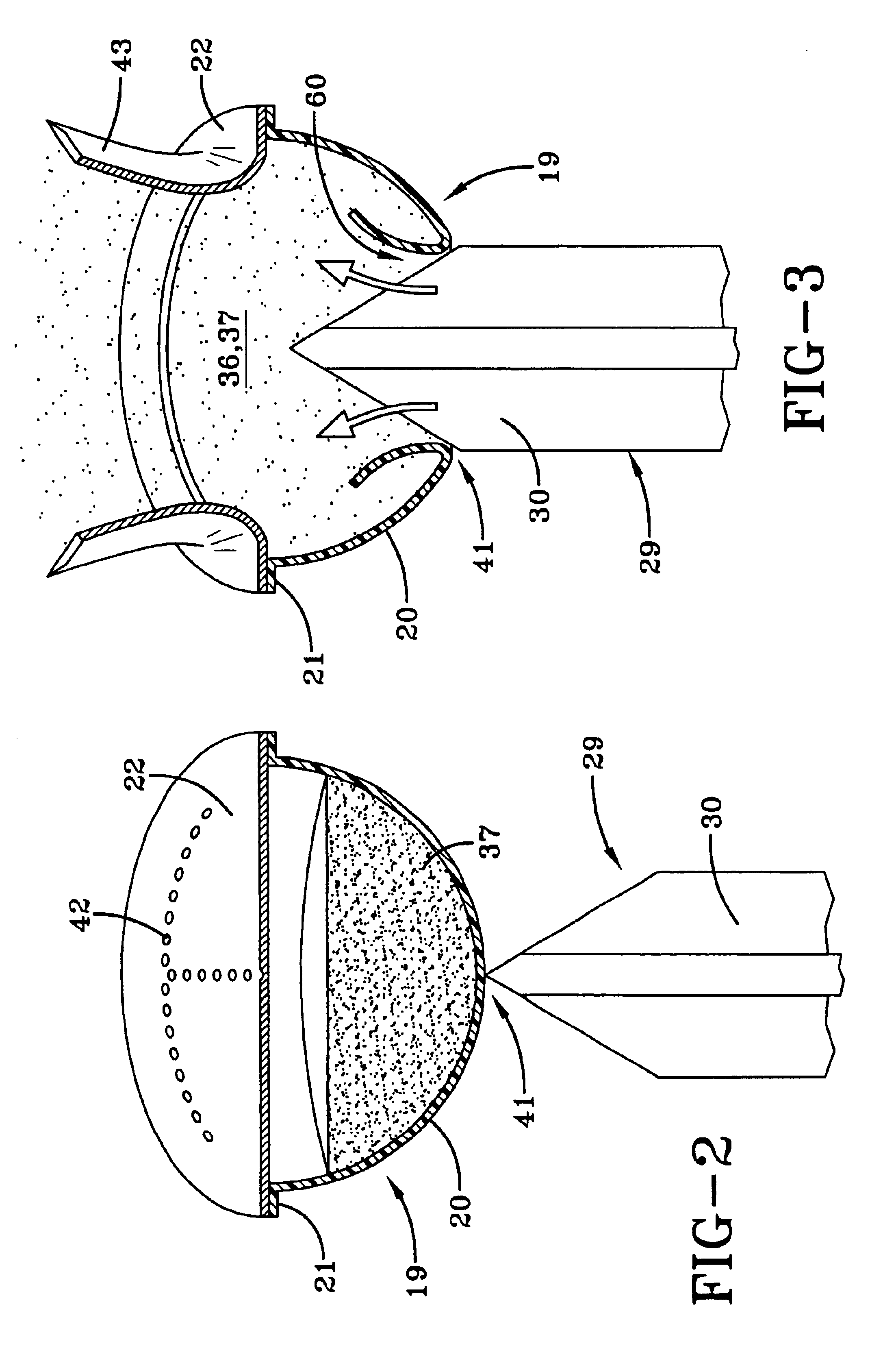
The base body 12 contains a first chamber 16, which has a cylindrical section 17 constructed as a pump cylinder and a section 18 connected thereto. At the end thereof is interchangeably inserted a second chamber 19 and is held there by the adaptor. The second chamber comprises a blister with a hemispherical, bowl-shaped plastic moulding 20 and an edge 21, onto which is sealed a discharge closure element 22 in the form of a metal foil or plastic film tightly sealing the second chamber. The blister is fixed at the edge 21 in tight manner between an upper...


PUM


Abstract

The object of the invention is to provide a method and a dispenser in which, compared with known dispensers, the fluid path design is simplified. The dispenser has a medium reservoir (19) containing a medium to be discharge during one discharge stroke of the dispenser (11). For this purpose a feed fluid flows through the medium reservoir and discharges the medium through a reservoir discharge opening. For producing a discharge stroke, the dispenser has an actuator (25), whose actuation at least indirectly leads to an impact spike (29) penetrating from the outside into the medium reservoir (19), so as to produce a connection between a pump (40) for a feed fluid and the medium reservoir. As a result of the pressure of the feed fluid flowing into the medium reservoir, at a point in the medium reservoir (19) differing from the entry point of the impact spike (29), an opening is formed.

Description

BACKGROUND OF THE INVENTIONThe invention relates to a method and to a dispenser for mixing and discharging a medium mixture mixed from two media.DE 19817417 A (corresponding to U.S. Ser. No. 09 / 554031) discloses a dispenser, in which a medium to be discharged, e.g. a powder, is received in a blister ring. The user operates an air pump cylinder and presses the blister ring against a hollow impact spike, which perforates a cover foil of a blister chamber. Through said opening, air enters the blister chamber and discharges the medium through the hollow impact spike. Thus, the air enters the medium chamber alongside or through the impact spike and passes out from the same again. This limits the line cross-section and the flow guidance for a good mixing.OBJECT OF THE INVENTIONAn object of the invention is to provide a method and dispenser simplifying the guidance of the media, which reduces the requirement for easy miscibility of the media and which improves the mixing process.SUMMARY OF...

Claims


Application Information

Patent Timeline
Patent Type & Authority Patents(United States)
IPC IPC(8): A61M15/00
CPCA61M15/0028A61M15/0036A61M2202/064A61M15/0041A61M11/02A61M2205/073
Inventor STIHL, ALEXANDER
Owner APTAR RADOLFZELL
Why Eureka
Try Eureka