Positioning unit with a plurality of indicators for guiding a needle

a technology of positioning unit and plurality of indicators, which is applied in the field of positioning unit for guiding a medical object, can solve the disadvantage of high loading of x-rays, and achieve the effect of facilitating visualization of movement information

Active Publication Date: 2020-11-12
SIEMENS HEALTHCARE GMBH
View PDF0 Cites 0 Cited by
  • Summary
  • Abstract
  • Description
  • Claims
  • Application Information

AI Technical Summary

Benefits of technology

[0014]According to one development, it is provided that the plurality of indicators are arranged such that the plurality of indicators lie on a same circle or a same envelope surface of a cylinder. In other words, the plurality of indicators may all be arranged on a circle. For example, at least three (e.g., exactly four) indicators are arranged on a circle. Alternatively, the plurality of indicators may all be arranged on a plurality of circles. In this case, at least three (e.g., exactly four) of the plurality of indicators are arranged on each of the circles. If the plurality of circles each have the same radius and only one axial displacement relative to one another, the indicators that are arranged on different circles are arranged on the same envelope surface of a cylinder. Respective circular planes of the plurality of circles extend, for example, parallel to one another. Overall, through the aforementioned arrangement, an advantageous visualization of the movement information is enabled.
[0015]According to one development, the securing unit is configured to arrange the positioning unit on the medical object such that a line of gravity that extends along a main extent of the medical object extends through the midpoint of the circle or the envelope surface. In other words, the securing unit is configured to arrange the positioning unit on the medical object such that the circle or the envelope surface, on which the plurality of indicators are arranged, encompass the medical object (e.g., a main extent direction). In this encompassing, the line of gravity of the medical object extends through the midpoint of the circle or the envelope surface. The expression of the midpoint of the envelope surface denotes herein a point on the rotationally symmetrical axis of the cylinder. The cylinder and the envelope surface of the cylinder do not have to be physically present. In other words, the envelope surface or the cylinder may be an imaginary geometrical object in order to describe the geometry of the plurality of indicators. Through the arrangement of the plurality of indicators around the central line of gravity of the medical object, a particularly intuitive guidance of the positioning unit may be enabled.
[0017]It is further provided that the indicating element includes two (e.g., round) plates that may each be arranged using a respective part of the securing unit independently of one another. On each of the two plates, at least three (e.g., four) of the plurality of indicators are arranged. For example, the two plates may be arranged on the medical object, by the securing unit, in a different longitudinal position in relation to the main extent direction of the medical object. Thereby, the securing unit is configured, for example, to arrange the two plates in relation to the medical object such that the line of gravity extends through a respective midpoint of the plates. In some exemplary embodiments, the two plates have no mechanical connection to one another. In this case, the relative positioning to one another is only fixed by the arrangement of both plates to the medical object. In other words, the two plates may be connected to one another indirectly by the medical object if both plates are arranged on the medical object. The securing unit may have two subelements, where each of the subelements is arranged on one of the two plates. In other words, each plate has a respective subelement of the securing unit. Each subelement arranged on a plate may be configured to arrange the respective plate on the medical object. In this way, the positioning unit may be configured to be particularly simple and compact.
[0020]According to one development, the positioning unit is configured to indicate, in a first illumination step, the direction in which the positioning unit is to be turned according to the movement information, and in a second illumination step, to indicate the direction in which the positioning unit is to be moved according to the movement information. The first illumination step and the second illumination step follow one another. For example, the first illumination step may take place before the second illumination step, or the second illumination step may take place before the first illumination step. Therein, the indication of the direction in which the positioning unit is to be turned may be at least partially shown with the same of the plurality of indicators as the indication of the direction in which the positioning unit is to be moved. “Turning” may herein be, for example, a rotary movement. “Movement” may be, for example, a translational position change. In other words, the first illumination step may relate exclusively to the rotation, and the second illumination step may relate exclusively to the translation of the positioning unit. For example, it is provided that the positioning unit is configured, in the first illumination step, to indicate exclusively the direction in which the positioning unit is to be turned and / or rotated according to the movement information. For example, the positioning unit is configured, in the second illumination step, to indicate exclusively the direction in which the positioning unit is to be moved and / or translationally moved according to the movement information. The positioning unit may thereby be configured to carry out the indication according to the first illumination step and the second illumination step partially or entirely by the same of the plurality of indicators. In this way, the number of indicators needed for this may be reduced.
[0027]The sensor unit may include an acceleration sensor that is arranged on the positioning unit. In this case, the sensor unit may be configured to determine the position and / or the orientation of the positioning unit based on the acceleration data of the acceleration sensor. In other words, the sensor unit may be configured to determine the position and / or the orientation of the positioning unit based on the acceleration data, similarly to an odometry. Thereby, the position determination may take place, starting from a reference position, by summation and / or integration of acceleration values contained in the acceleration data. The reference position may be pre-determined, for example, using a holding element that may be arranged on a patient support. The sensor unit may be configured, starting from the reference position, to determine the current position and / or orientation of the positioning unit, starting from the reference position by summing and / or integration of the acceleration values. For example, only the acceleration values that have been acquired since the last removal of the positioning system from the reference position (e.g., the holding element) are thereby summed or integrated. In this way, the position and / or orientation of the positioning unit may be determined in an easy manner.

Problems solved by technology

The high loading with X-rays is disadvantageous thereby.

Method used


Image

  • Positioning unit with a plurality of indicators for guiding a needle
  • Positioning unit with a plurality of indicators for guiding a needle
  • Positioning unit with a plurality of indicators for guiding a needle

Examples


Embodiment Construction

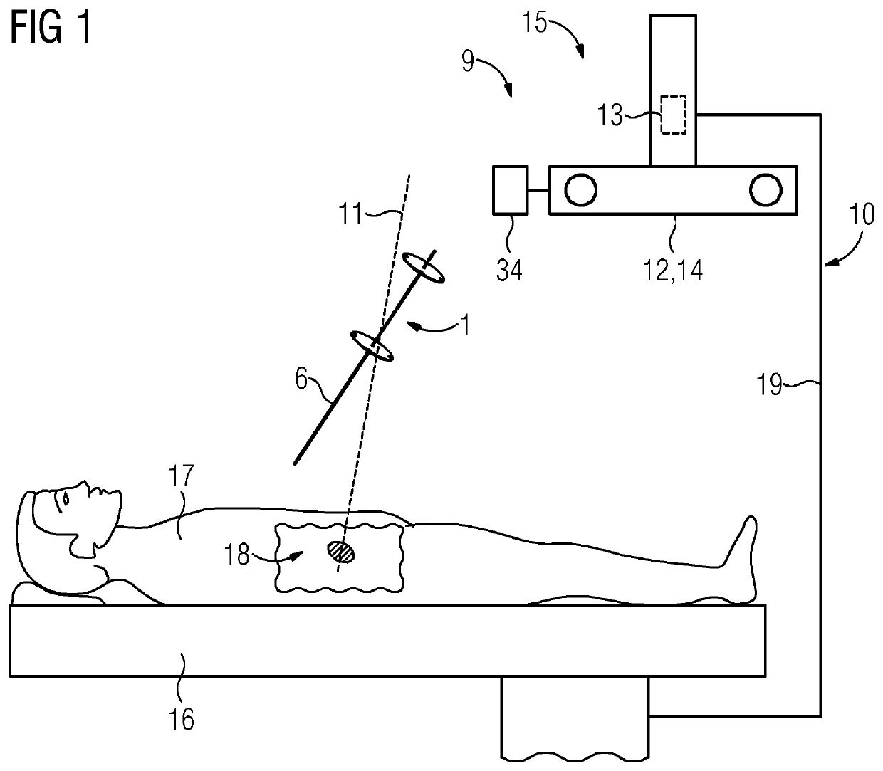
[0041]FIG. 1 shows one embodiment of a medical system 10 that includes a positioning unit 1, a patient support 16, and an immovable module 15. In an intended operating state, the immovable module 15 is arranged, for example, such that the immovable module 15 is immovable relative to the patient support 16. For example, the module 15 is mechanically connected to the patient support 16 by a connecting element 19. The relative position between the module 15 and the patient support 16 is defined by the connecting element 19 and, for example, is constant at least during an operation of the system 10. Alternatively, the immovable module 15 may be arranged in any other way in the pre-determined position relative to the patient support 16. For example, the module 15 is arranged on a wall or a ceiling of a room in which the patient support 16 is located. The patient support 16 may be, for example, an operating table or a hospital bed.

[0042]The patient support 16 is configured for holding or ...


PUM


Abstract

A positioning unit for guiding a medical object such as a needle includes a securing unit by which the positioning unit may be arranged on the medical object. In order to enable an improved guidance for the medical object, an indicating element with a plurality of indicators is provided. The indicating element is arranged in a fixed position relative to the securing unit. An acquisition unit acquires an item of movement information. The positioning unit is configured to control the plurality of indicators dependent upon the movement information.

Description

[0001]This application claims the benefit of German Patent Application No. DE 10 2019 206 825.1, filed on May 10, 2019, which is hereby incorporated by reference in its entirety.BACKGROUND[0002]The present embodiments relate to a positioning unit for guiding a medical object.[0003]In the context of medical treatments, it is often necessary to introduce a medical needle in a targeted manner (e.g., along a precisely specified needle path or a previously planned trajectory) into a medical target object (e.g., a patient or a simulator for simulating the patient). A simulator may also be referred to as a dummy. With the aid of the dummy, the patient or the medical treatment on the patient may be simulated. For example, for a treatment in the interior of the body of the patient (e.g., on internal organs), an exact guidance of the needle along the needle path or the planned trajectory is important. By this, the guidance of the needle along the correct path between tissues and bones and the...

Claims


Application Information

Patent Timeline
Patent Type & Authority Applications(United States)
IPC IPC(8): A61B17/34A61B90/13
CPCA61B2017/3405A61B17/3403A61B90/13A61B2090/309A61B34/20A61B2034/2046A61B2034/2048A61B2034/107A61B2034/2063A61B2090/3983A61B2017/00716A61B2034/2051A61B2090/3966A61B2034/2055A61B2090/0807A61B90/11
Inventor REGENSBURGER, ALOISMEHLDAU, HEIKOALZAGA, AMILCAR
Owner SIEMENS HEALTHCARE GMBH
Why Eureka
Try Eureka