Pivoting implement hitch extension

a technology of implements and bending bars, which is applied in the direction of towing devices, tractor-trailer combinations, agriculture, etc., can solve the problems of increasing bending forces, tractors with sufficient power to otherwise operate such mowers, and often not having a drawbar with sufficient strength to bear the weight of the front hitch end of the mower, etc., to achieve the effect of reducing bending forces and reducing them

Inactive Publication Date: 2005-04-12
SCHULTE INDS
View PDF12 Cites 30 Cited by
  • Summary
  • Abstract
  • Description
  • Claims
  • Application Information

AI Technical Summary

Benefits of technology

To reduce bending forces on the drawbar compared to prior art devices having a yaw axis equidistant from the front and rear universal joints, the pitch axis can be located forward of the yaw axis, and to reduce them even further, the pitch axis can be located forward of the drawbar hole.

Problems solved by technology

These pitch and roll axes can be provided by a ball and socket connection however the degree of movement allowed is often not sufficient for the particular application.
Tractors with sufficient power to otherwise operate such mowers often do not have a drawbar with sufficient strength to bear the weight of the front hitch end of the mower.
The drawbar cantilevers out from the tractor, and when excessive weight is placed on the rear end of the drawbar, it can bend.
Especially with larger rotary mowers, the increased bending forces can be problematic, requiring a heavier drawbar than is normally provided on a tractor with sufficient power to otherwise operate the mower satisfactorily.

Method used


Image

  • Pivoting implement hitch extension
  • Pivoting implement hitch extension
  • Pivoting implement hitch extension

Examples


Embodiment Construction

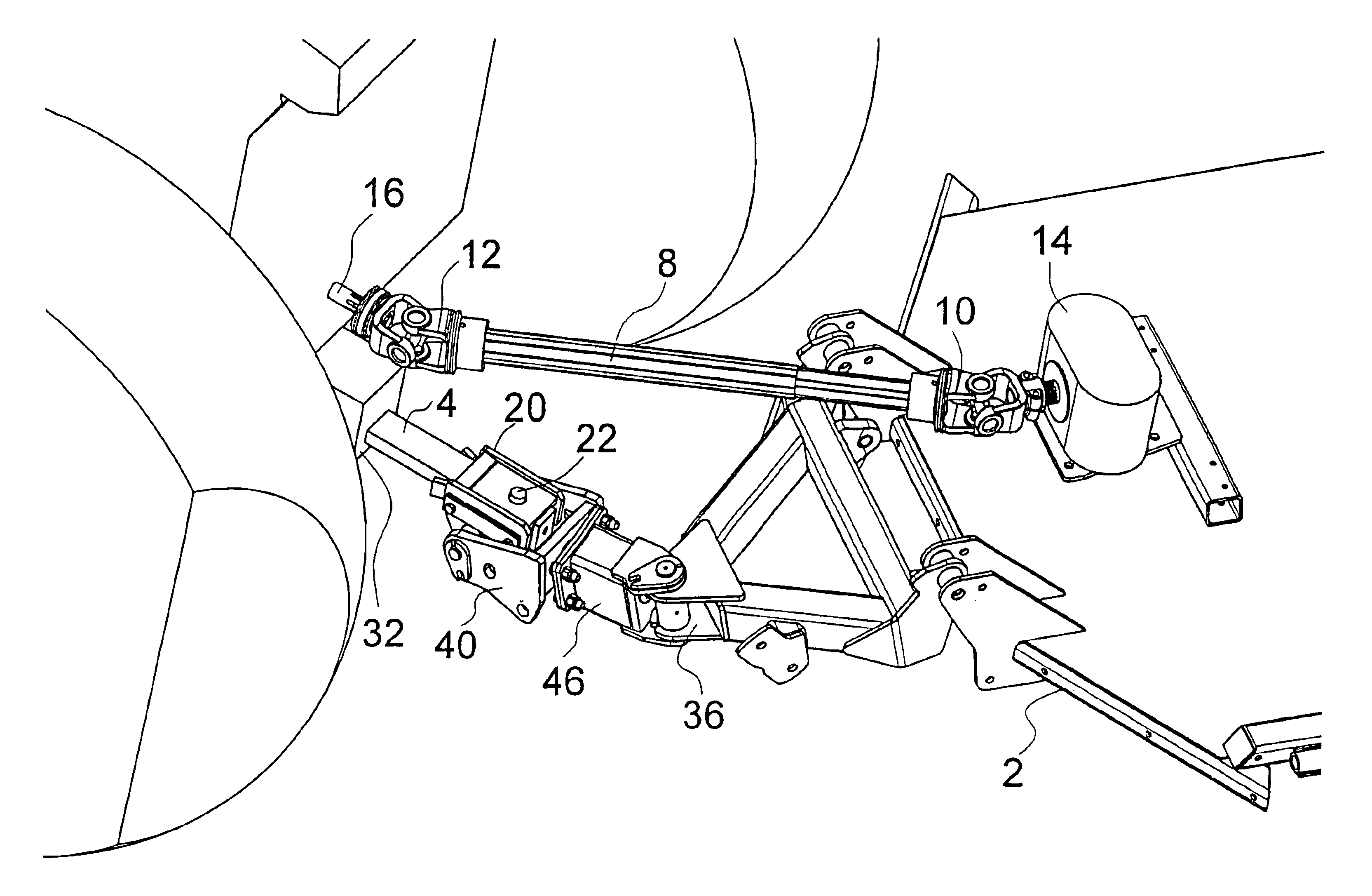
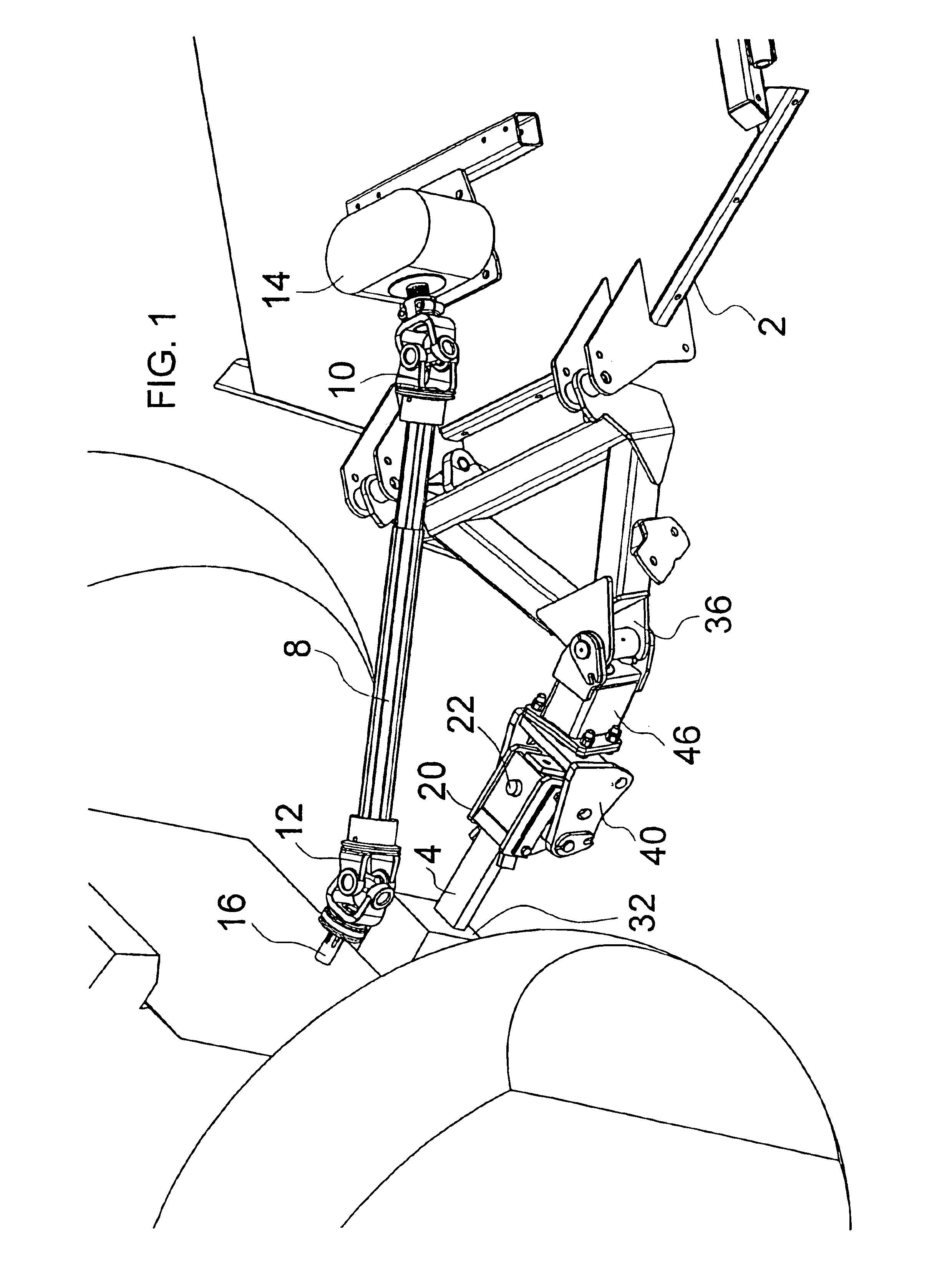
FIGS. 1-4 illustrate a hitch extension apparatus 1 for attaching an implement, illustrated as a rotary mower unit 2, to a tractor drawbar 4 for towing in an operating travel direction T. The tractor drawbar 4 defines a drawbar hole 6. The rotary mower unit 2 comprises a drive shaft 8 having a rear universal joint 10 at a rear end thereof connected to a driveline 14 of the rotary mower unit 2, and a front universal joint 12 at a front end thereof adapted for attachment to a tractor power take off 16 with a coupler or the like.

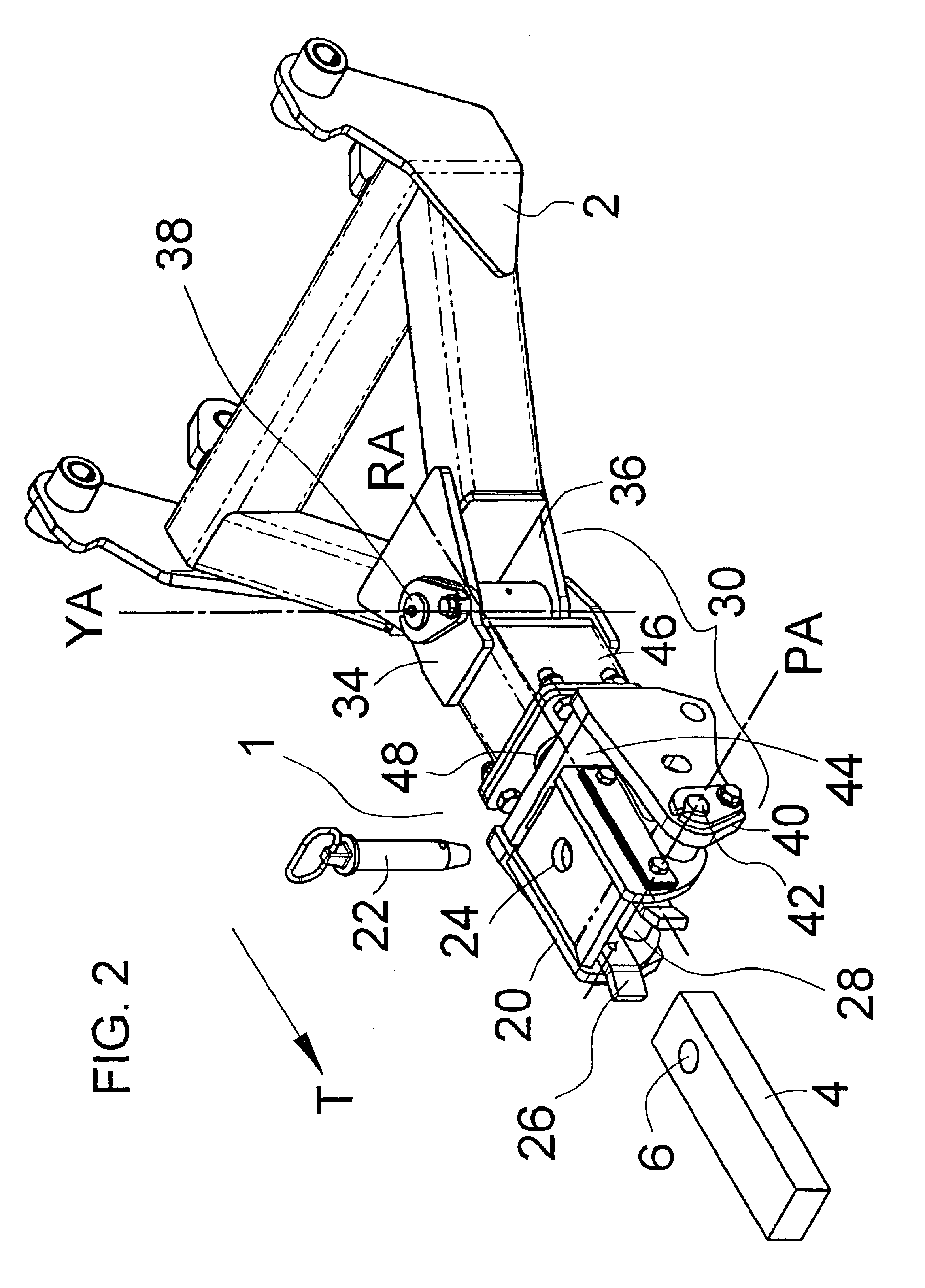
The hitch extension apparatus 1 comprises a first member, illustrated as sleeve 20, adapted for attachment to the tractor drawbar 4 by insertion of a drawbar pin 22 through the drawbar hole 6 and through corresponding top and bottom draw pin holes 24 defined by upper and lower portions of the sleeve 20. The sleeve 20 slides over the drawbar 4. The drawbar 4 fits the drawbar location 28 defined by the walls 26 of the sleeve 20 such that the sleeve 20 is substanti...


PUM


Abstract

A hitch extension apparatus for attaching an implement with a pto driven drive shaft having front and rear universal joints to a tractor drawbar. The apparatus comprises a first member adapted for attachment to the tractor drawbar by insertion of a drawbar pin through the drawbar such that the first member is fixed with respect to the drawbar. An extension member is pivotally attached to the first member about a horizontal pitch axis oriented perpendicular to the travel direction, and about a horizontal roll axis oriented parallel to the operating travel direction. The extension member defines a pivotal attachment location rearward of the draw pin hole adapted for pivotal attachment of the implement about a vertical yaw axis located equidistant from the front and rear universal joints when the drive shaft is connected to the tractor power take off. The pitch axis can be located forward of the yaw axis, and forward of the draw pin hole in order to reduce bending forces on the drawbar.

Description

CROSS REFERENCE TO PRIOR APPLICATIONThis application claims priority to Canadian Patent Application No. 2,426,630, filed on Apr. 28, 2003, which is incorporated herein by reference.TECHNICAL FIELDThis invention is in the field of towed implements and in particular power take off driven implements.BACKGROUND OF THE INVENTIONTypically a tractor drawbar extends rearward from the tractor and has a vertical drawbar pin hole for attachment of an implement about a substantially vertical yaw axis so that the implement can pivot with respect to the tractor during turns. In a typical implement hitch it is also desirable to allow the implement to move independently of the tractor so that the implement can follow the ground. It is desired that the implement can pivot about a roll axis that is substantially parallel to the drawbar, and also about a pitch axis that is substantially perpendicular to the drawbar. These pitch and roll axes can be provided by a ball and socket connection however the ...

Claims


Application Information

Patent Timeline
Patent Type & Authority Patents(United States)
IPC IPC(8): B60D1/167B60D1/00
CPCB60D1/075B60D1/167B60D2001/546
Inventor COLISTRO, VINCENT
Owner SCHULTE INDS
Why Eureka
Try Eureka