Systems and methods for securing a rotor apparatus

a technology of securing systems and rotors, applied in the field of rotors, to achieve the effect of reducing contact, facilitating stacked pairs, and reducing the bending force of the fastener

Inactive Publication Date: 2014-06-19
PILLER USA INC
View PDF3 Cites 7 Cited by
  • Summary
  • Abstract
  • Description
  • Claims
  • Application Information

AI Technical Summary

Benefits of technology

[0020]In an embodiment, the first and second laminations can also be oriented such that the bottom face of the first lamination contacts the top face of the second lamination (e.g., such that the top and bottom faces of each lamination are oriented in the same direction). Such an embodiment can be useful, for example, to accommodate the presence of deformations such as those shown in FIG. 2, by enabling laminations that are slightly curved and / or otherwise modified via the removal process to nest within one another.
[0021]To account for the fact that laminations may vary slightly in thickness due to variations in thickness along the length of a rolled material, in an embodiment, stacked pairs of laminations can be placed in opposing and / or offset orientations relative to one another. For example, each successive stacked pair of laminations can be rotationally offset from the next adjacent pair by a known angle. Visible indicators on the laminations can be used to facilitate orienting the stacked pairs relative to one another, as well as orienting the individual laminations relative to one another.
[0022]The orifices within the laminations through which the fasteners pass, and / or the fasteners themselves, can define an envelope, which corresponds to a maximum space able to be occupied by a fastener while reducing contact between the fastener and the laminations during rotation of the rotor apparatus. In an embodiment, one or more fasteners can have a volume of material less than the volume of the envelope. For example, a fastener could have an annular shape, e.g., that of a cylinder with an axial bore from which material has been removed. In another embodiment, a fastener could have an “I-beam” shape, e.g., a generally cylindrical body having portions in the periphery thereof from which material has been removed. Generally, removal of material from the “envelope” occupied by a fastener can reduce the bending forces on the fastener, such that a greater angular velocity of the rotor apparatus can be achieved while reducing contact between the fasteners and the laminations.

Problems solved by technology

For example, when one or more fasteners are off-set from the center of the rotor assembly, rotation thereof can impart a centrifugal force to the fasteners, causing bending thereof.

Method used


Image

  • Systems and methods for securing a rotor apparatus
  • Systems and methods for securing a rotor apparatus
  • Systems and methods for securing a rotor apparatus

Examples


Embodiment Construction

[0057]While embodiments usable within the scope of the present disclosure are described with reference to laminated rotor assemblies usable in a homopolar alternator, such as those described in U.S. Pat. Nos. 5,969,497 and 5,929,548, incorporated by reference above, it should be understood that embodiments usable within the scope of the present disclosure can be used in conjunction with any type of rotating machine, or any other type of device that includes one or more parts formed using laminated technology.

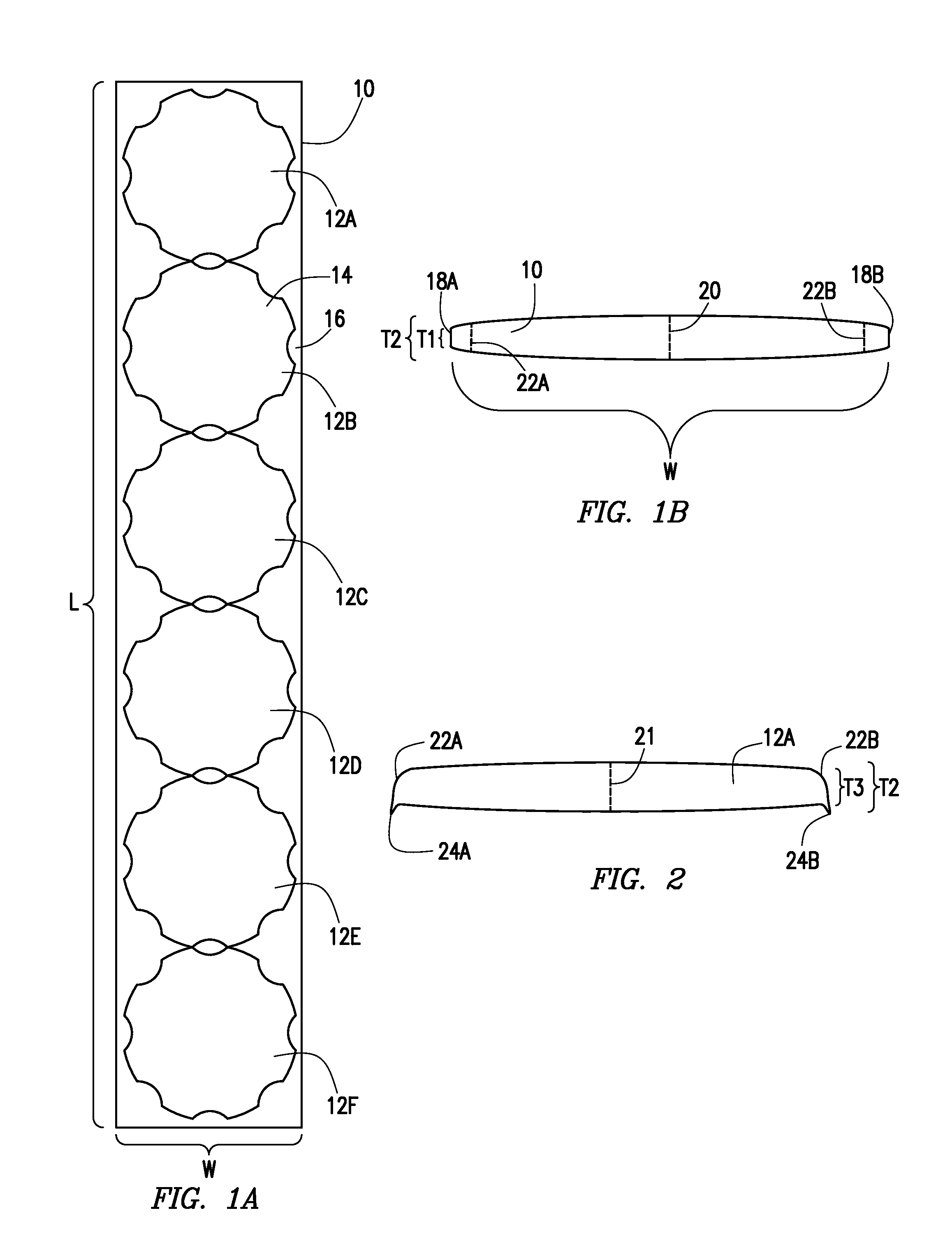
[0058]FIG. 6A depicts a top view of sheet of rolled, magnetically permeable material (76) (e.g., magnetic steel or a similar material), having a width (W2) and length (L2). FIG. 6B depicts a side view thereof. As described above, the sheet (76) can have a variable thickness, as illustrated in FIG. 6B, which depicts the sheet (76) having a thickness (T4) at the centerline (78) thereof greater than the thickness (T5) at the outer edges (82A, 82B). The outlines of twelve lamination...


PUM

PropertyMeasurementUnit
thicknessaaaaaaaaaa
thicknessaaaaaaaaaa
diameteraaaaaaaaaa

Abstract

Rotors apparatus usable in energy storage devices and power systems include a plurality of laminations having a center and at least one orifice spaced a distance from the center, and at least one fastener extending through the orifice. The one or more fasteners, the one or more orifices, or combinations thereof are sized to reduce contact between the fasteners and the laminations during rotation of the rotor apparatus. The fasteners and orifices can define an envelope, corresponding to the maximum space able to be occupied by a fastener to reduce contact between the fastener and the laminations, and one or more fasteners can have a volume of material less than the volume of the envelope to reduce bending forces on the fastener.

Description

CROSS REFERENCE TO RELATED APPLICATIONS[0001]The present application claims priority to the U.S. Provisional Application for Patent having the Application Ser. No. 61 / 738,391, filed Dec. 17, 2012; the U.S. Provisional Application for Patent having the Application Ser. No. 61 / 739,548, filed Dec. 19, 2012; and the U.S. Provisional Application for Patent having the Application Ser. No. 61 / 746,440 filed Dec. 27, 2012. Each of the above-referenced applications is incorporated by reference herein in its entirety.FIELD OF THE PRESENT DISCLOSURE[0002]Embodiments usable within the scope of the present disclosure relate, generally, to rotor apparatus, e.g., for use in rotating machines and methods of constructing and / or assembling such assemblies, and more specifically, to rotors made from layered materials (e.g., laminations) usable in flywheel alternators and / or similar energy storage devices.BACKGROUND[0003]Numerous electrical machines operate by means of interaction between a magnetic fie...

Claims


Application Information

Patent Timeline
Patent Type & Authority Applications(United States)
IPC IPC(8): H02K7/02H02K15/02
CPCH02K15/02H02K7/025Y02E60/16Y10T29/49012Y10T74/2119
Inventor ANDREWS, JAMESHUDSON, ROBERT
Owner PILLER USA INC
Why Eureka
Try Eureka