Multiple drive-path transmission with torque-splitting differential mechanism

a technology of torque splitting differential and drive path transmission, which is applied in the direction of mechanical equipment, transportation and packaging, etc., can solve the problems of reducing affecting the reliability of rotary-wing aircraft, and a number of unfortunate design limitations, so as to reduce the size and/or weight of bull gears.

Active Publication Date: 2012-03-27
TEXTRON INNOVATIONS
View PDF11 Cites 7 Cited by
  • Summary
  • Abstract
  • Description
  • Claims
  • Application Information

AI Technical Summary

Benefits of technology

[0007]There is a need for a means for transmitting torque to a bull gear in a manner which allows for the use of a reduced size and / or weight bull gear.
[0008]Therefore, it is an object of the present invention to provide a means for transmitting torque to a bull gear in a manner which allows for the use of a reduced size and / or weight bull gear.
[0011]The present invention provides significant advantages, including: (1) providing a low-cost and low-weight means for reducing gear tooth bending forces acting on the teeth of a bull gear; (2) reducing the weight and / or size of a bull gear; and (3) providing multiple inputs to a single bull gear while avoiding force fights among the multiple force paths and while allowing phase differences and / or lead / lag between multiple input gears.

Problems solved by technology

While this configuration is common, it remains fraught with a number of unfortunate design limitations.
More specifically, while it is often desirable to drive a mast with high torque, the size and / or weight of a bull gear capable of transmitting the high torque over a sufficiently long period of time may prove to be a significant limiting factor.
Prevention of gear tooth failure is imperative because failure of a bull gear may lead to a catastrophic rotary-wing aircraft failure.
This is a seemingly elegant solution, but in practice, a number of problems occur in implementing the solution.
Further, previous attempts at driving a bull gear with multiple inputs were troubled by less than optimal distribution of torque between the multiple drive paths and the force fights which occur between the two drive paths when a phase difference or lead / lag situation occurs between the drive paths.
Since the atypical forces transferred to the teeth of the bull gear may easily be of very high magnitude (at least higher than the force normally transferred to the teeth of the bull gear in a single transfer gear configuration), this force fighting is incompatible with the goal of reducing the forces transmitted to the teeth of the bull gear.

Method used


Image

  • Multiple drive-path transmission with torque-splitting differential mechanism
  • Multiple drive-path transmission with torque-splitting differential mechanism
  • Multiple drive-path transmission with torque-splitting differential mechanism

Examples


Embodiment Construction

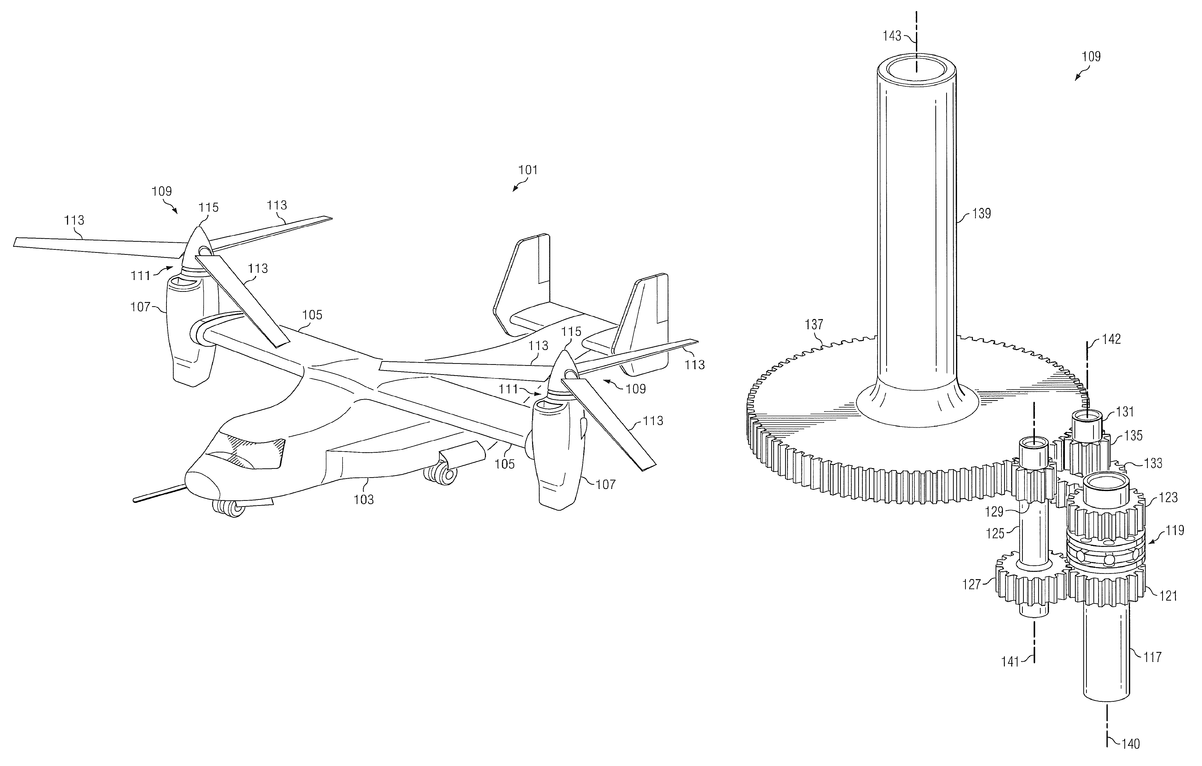
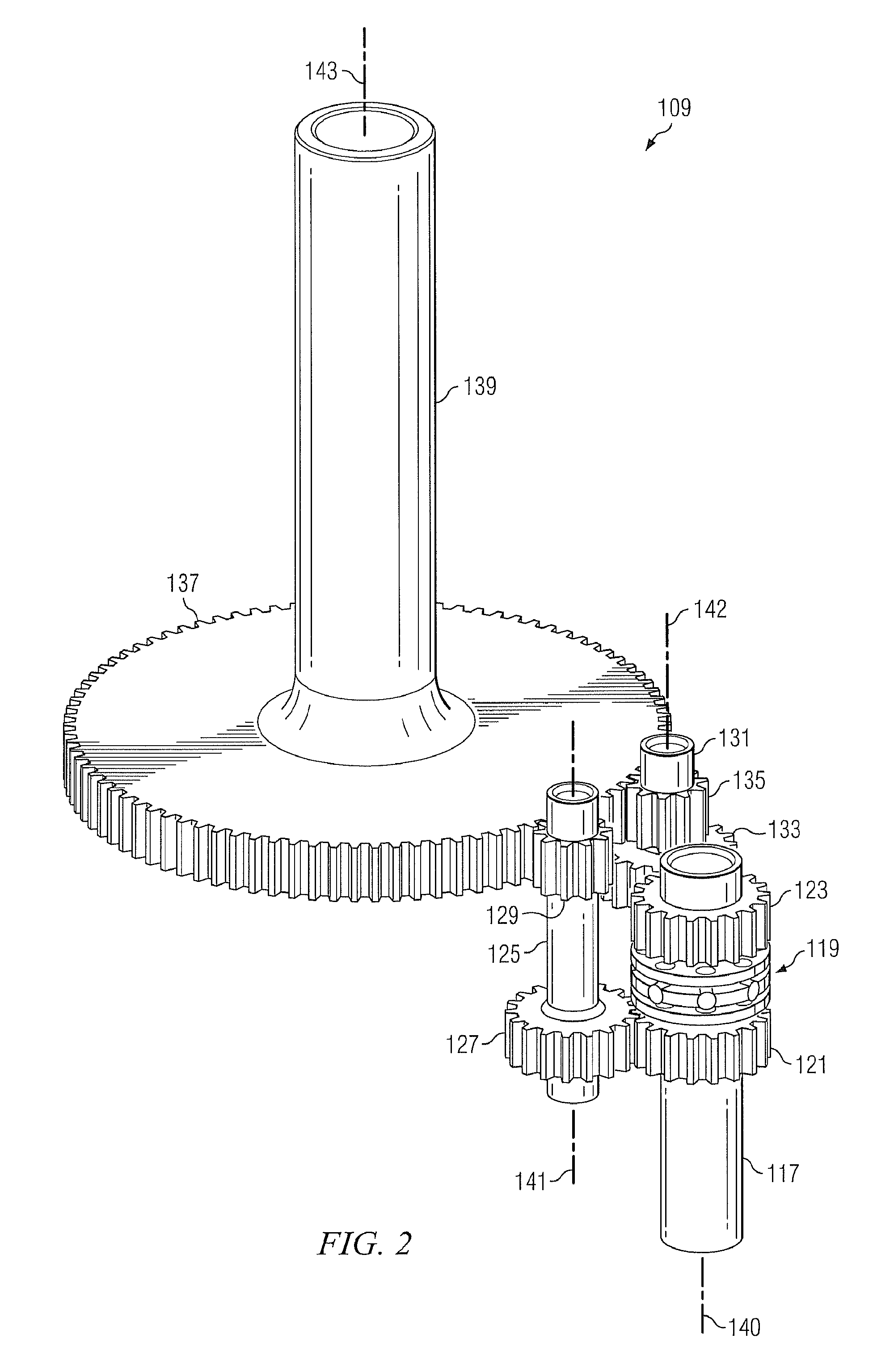
[0026]The present invention represents the discovery that a torque-splitting differential mechanism can be advantageously used to deliver torque through multiple drive paths to a bull gear. While specific reference is made to using the present invention with tiltrotor rotary-wing aircraft, the transmission of the present invention may alternatively be used to transfer torque in any appropriate type of application.

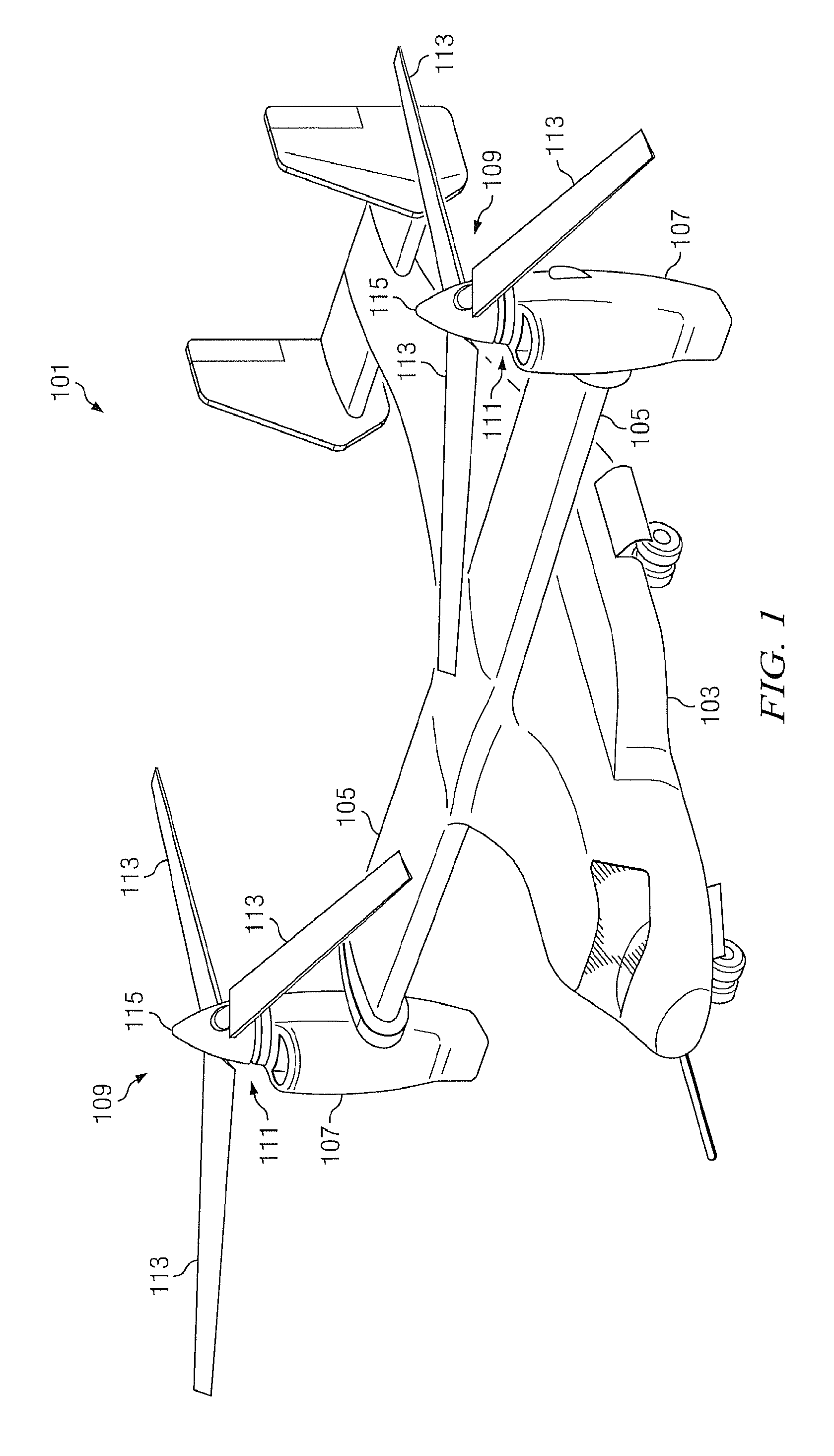
[0027]FIG. 1 depicts a tiltrotor rotary-wing aircraft incorporating the transmission of the present invention. FIG. 1 illustrates a tiltrotor aircraft 101 in a helicopter mode of flight operation. Aircraft 101 comprises a fuselage 103 with attached wings 105. Nacelles 107 are carried at the outboard ends of wings 105 and are rotatable between the helicopter-mode position shown and a forward-facing airplane-mode position (not shown). Nacelles 107 carry engines and transmissions 109 for powering rotor systems 111 in rotation. It will be appreciated that an engine may be an in...


PUM


Abstract

A transmission for a rotary-wing aircraft has a differential torque-splitting mechanism associated with an input shaft. The differential has a drive disk coaxial with the shaft and integral in rotation with the shaft, a first driven member coaxial with the shaft and generally adjacent the drive disk, and a second driven member coaxial with the shaft and generally adjacent the drive disk. At least one pin engages each of the drive disk, the first driven member, and the second driven member. The first driven member is configured to drive a first transfer gear, and the second driven member is configured to drive a second transfer gear for supplying torque to a bull gear associated with a rotor mast.

Description

TECHNICAL FIELD[0001]The present invention relates generally to the field of rotary-wing aircraft and more particularly to the field of power transmissions for rotary-wing aircraft.DESCRIPTION OF THE PRIOR ART[0002]The driveshaft, or mast, of a rotary-wing aircraft is typically outfitted with a means for carrying rotor blades in a manner such that the rotor blades are capable of selectively producing lift when the mast is rotated. Of the rich variety of means known for transferring torque to a mast, a common configuration is to associate the mast with a single large bull gear (either by connecting the bull gear to the mast with splines or by forming the bull gear integrally with the mast) and driving the bull gear with a transfer gear. While this configuration is common, it remains fraught with a number of unfortunate design limitations.[0003]More specifically, while it is often desirable to drive a mast with high torque, the size and / or weight of a bull gear capable of transmitting...

Claims


Application Information

Patent Timeline
Patent Type & Authority Patents(United States)
IPC IPC(8): B64C27/08
CPCB64C27/14F16H1/22Y10T74/19005
Inventor STAMPS, FRANK B.SMITH, DUDLEYKILMAIN, CHARLES J.EHINGER, RYANCOLLINS, BOB
Owner TEXTRON INNOVATIONS
Why Eureka
Try Eureka