Can end and method for fixing the same to a can body

a technology for can ends and can bodies, applied in the field of can end and the same fixing to the can body, can solve the problems of narrow annular flanges of chucks that are susceptible to damage and the risk of scuffing

Inactive Publication Date: 2005-04-12
CROWN PACKAGING TECH
View PDF62 Cites 65 Cited by
  • Summary
  • Abstract
  • Description
  • Claims
  • Application Information

AI Technical Summary

Problems solved by technology

There is a risk of scuffing if this narrow annulus slips.
Furtherm

Method used


Image

  • Can end and method for fixing the same to a can body
  • Can end and method for fixing the same to a can body
  • Can end and method for fixing the same to a can body

Examples


Embodiment Construction

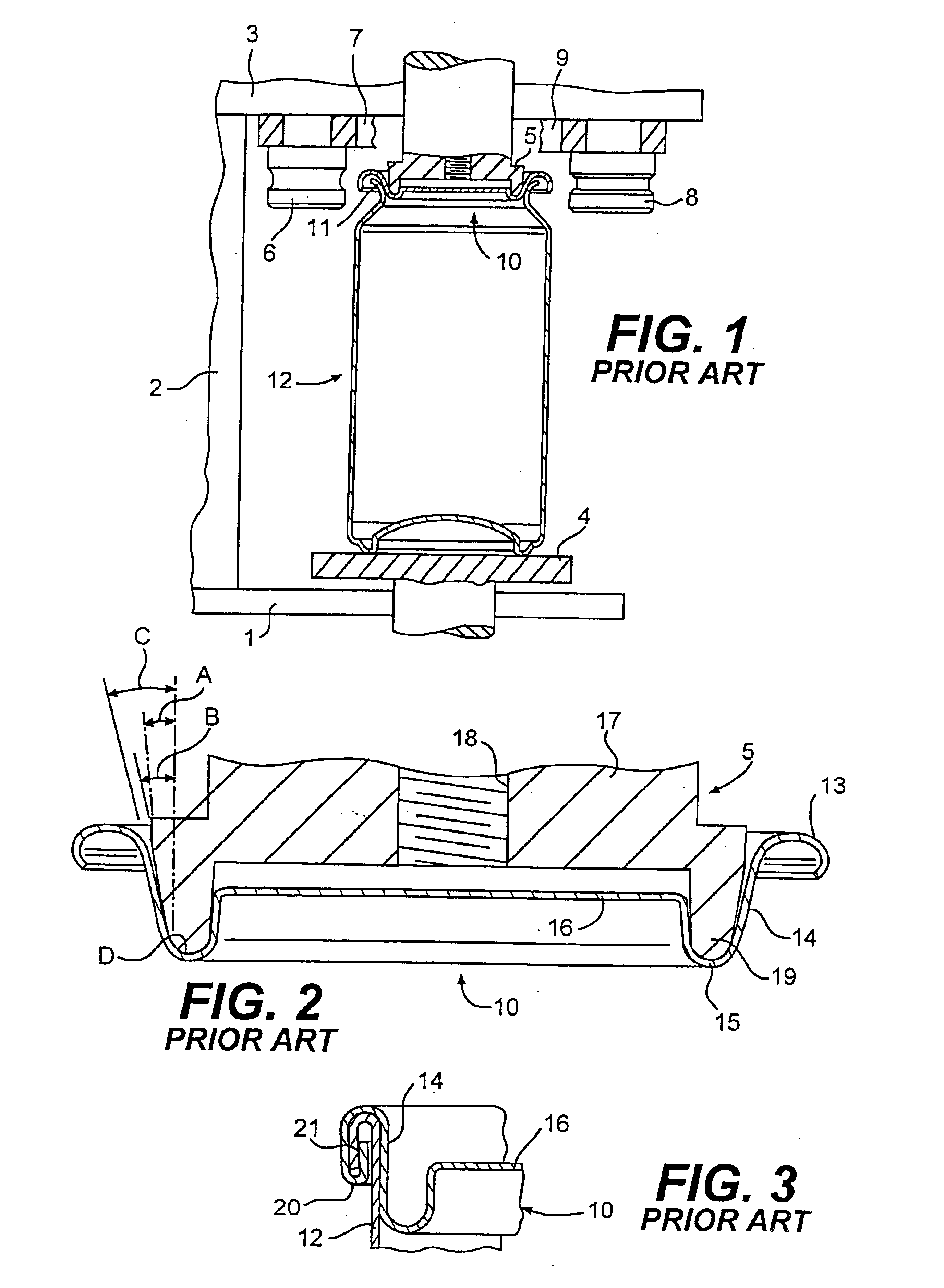
In FIG. 1, apparatus for forming a double seam comprises a base plate 1, an upright 2 and a top plate 3.

A lifter 4 mounted in the base plate is movable towards and away from a chuck 5 mounted in the top plate. The top plate supports a first operation seaming roll 6 on an arm 7 for pivotable movement towards and away from the chuck. The top plate also supports a second operation seaming roll 8 on an arm 9 for movement towards and away from the chuck after relative motion as between the first operation roll and can end on the chuck creates a first operation seam.

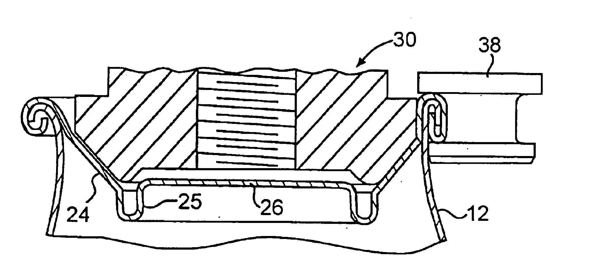
As shown in FIG. 1 the chuck 5 holds a can end 10 firmly on the flange 11 of a can body 12 against the support provided by the lifter plate 4. Each of the first operation roll 6 and second operation roll 7 are shown clear of chuck before the active seam forming profile of each roll is moved in turn to form the curl of the can end and body flange to a double seam as shown in FIG. 3.

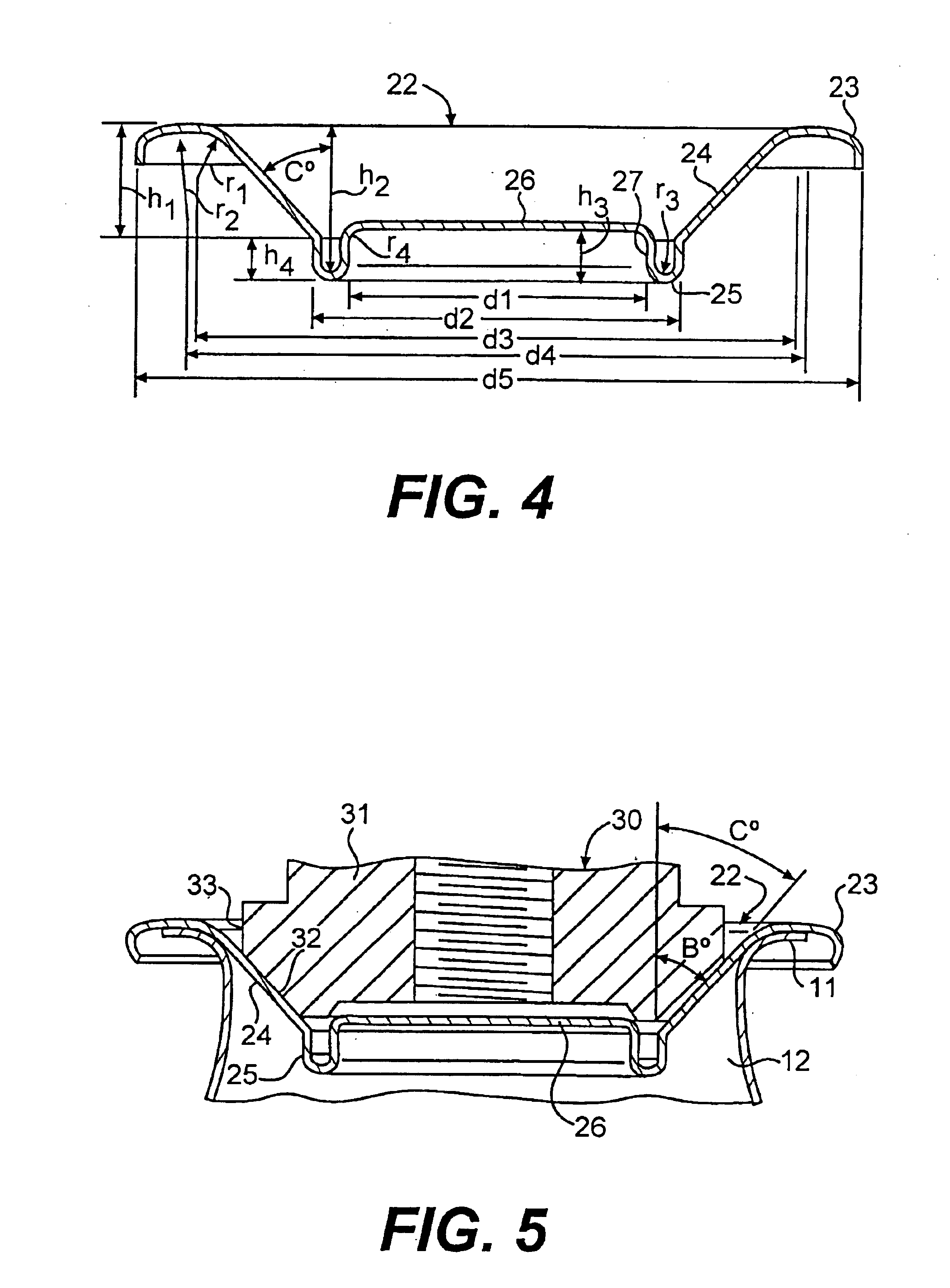
FIG. 2 shows on an enlarged scale the chuck 5 ...


PUM

PropertyMeasurementUnit
Angleaaaaaaaaaa
Angleaaaaaaaaaa
Angleaaaaaaaaaa

Abstract

A can end includes a peripheral cover hook a chuck wall dependent from the interior of the cover hook, an outwardly concave annular reinforcing bead extending radially inwards from the chuck wall, and a central panel supported by an inner portion of the reinforcing bead, characterized in that, the chuck wall is inclined to an axis perpendicular to the exterior of the central panel at an angle between 20° and 60°, and the concave cross-sectional radius of the reinforcing bead is less than 0.75 mm.

Description

BACKGROUND OF THE INVENTIONThis invention relates to an end wall for a container and more particularly but not exclusively to an end wall of a can body and a method for fixing the end wall to the can body by means of a double seam.U.S. Pat. No. 4,093,102 (KRASKA) describes can ends comprising a peripheral cover hook, a chuck wall dependent from the interior of the cover hook, an outwardly concave annular re-inforcing bead extending radially inwards from the chuck wall and a central panel joined to an inner wall of the reinforcing bead by an annular outwardly convex bead. This can end is said to contain an internal pressure of 90 psi by virtue of the inclination or slope of the chuck wall, bead outer wall and bead inner wall to a line perpendicular to the centre panel. The chuck wall slope D° is between 14° and 16°, the outer wall slope E is less than 4° and the inner wall slope C° is between 10 and 16° leading into the outwardly convex bead. We have discovered that improvements in m...

Claims


Application Information

Patent Timeline
IPC IPC(8): B21D51/30B21D51/32B21D51/26B21D51/44B65B51/09B65D1/12B65D6/28B65D6/30B65D8/06B65D8/20B65D17/34B65D21/032
CPCB21D51/32B65D7/36B65D17/08Y10S220/906B65D2517/0062
Inventor BRIFCANI, MOUAYED MAMDOOHHINTON, PETER JAMESKYSH, MARK CHRISTOPHER
Owner CROWN PACKAGING TECH
Why Eureka
Try Eureka