Mechanical bladder pump

a technology of mechanical bladder and pump, which is applied in the direction of piston pump, borehole/well accessories, survey, etc., can solve the problems of limited existing system, high cost of sample collection equipment, and inability to meet the needs of sampling, etc., and achieves low cost, high portability and mobility, and relatively small power supply

Inactive Publication Date: 2005-04-12
KEJR
View PDF11 Cites 22 Cited by
  • Summary
  • Abstract
  • Description
  • Claims
  • Application Information

AI Technical Summary

Benefits of technology

A further object of the present invention is to provide a bladder pump that can be operated with a relatively small power supply, that is highly portable and mobile; is inexpensive to manufacture, maintain and operate; is capable of a long operating life; and that will meet or exceed the flow rate requirements for environmental sampling using low-flow, minimal draw down methods.

Problems solved by technology

While gas driven bladder pumps are commonly used for collecting representative groundwater samples, there are some limitations to existing systems.
Two of these limitations are the amount of equipment required to conduct sample collection and the cost.
The collection of samples with this system is expensive, especially if the bladder pumps are dedicated to the wells as recommended by regulatory guidelines.
Although the gas driven bladder pump provides high quality samples, it is expensive to purchase and operate, as outlined above.

Method used


Image

  • Mechanical bladder pump
  • Mechanical bladder pump
  • Mechanical bladder pump

Examples


Embodiment Construction

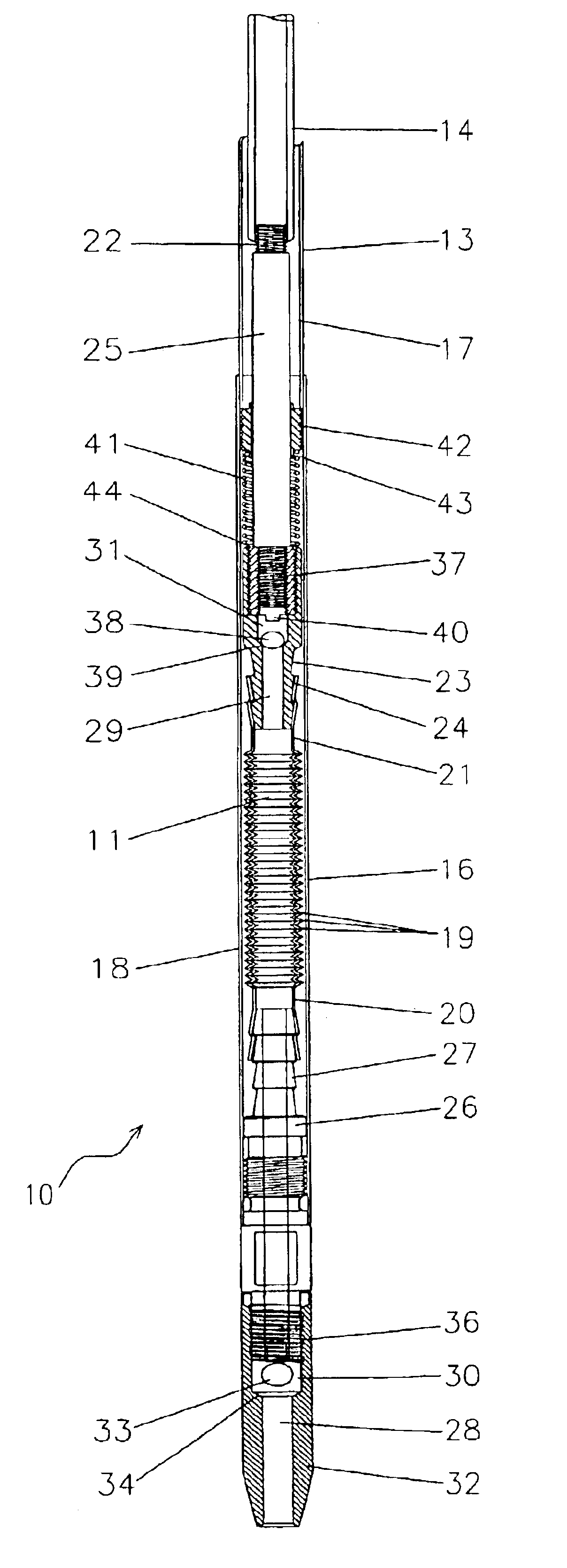
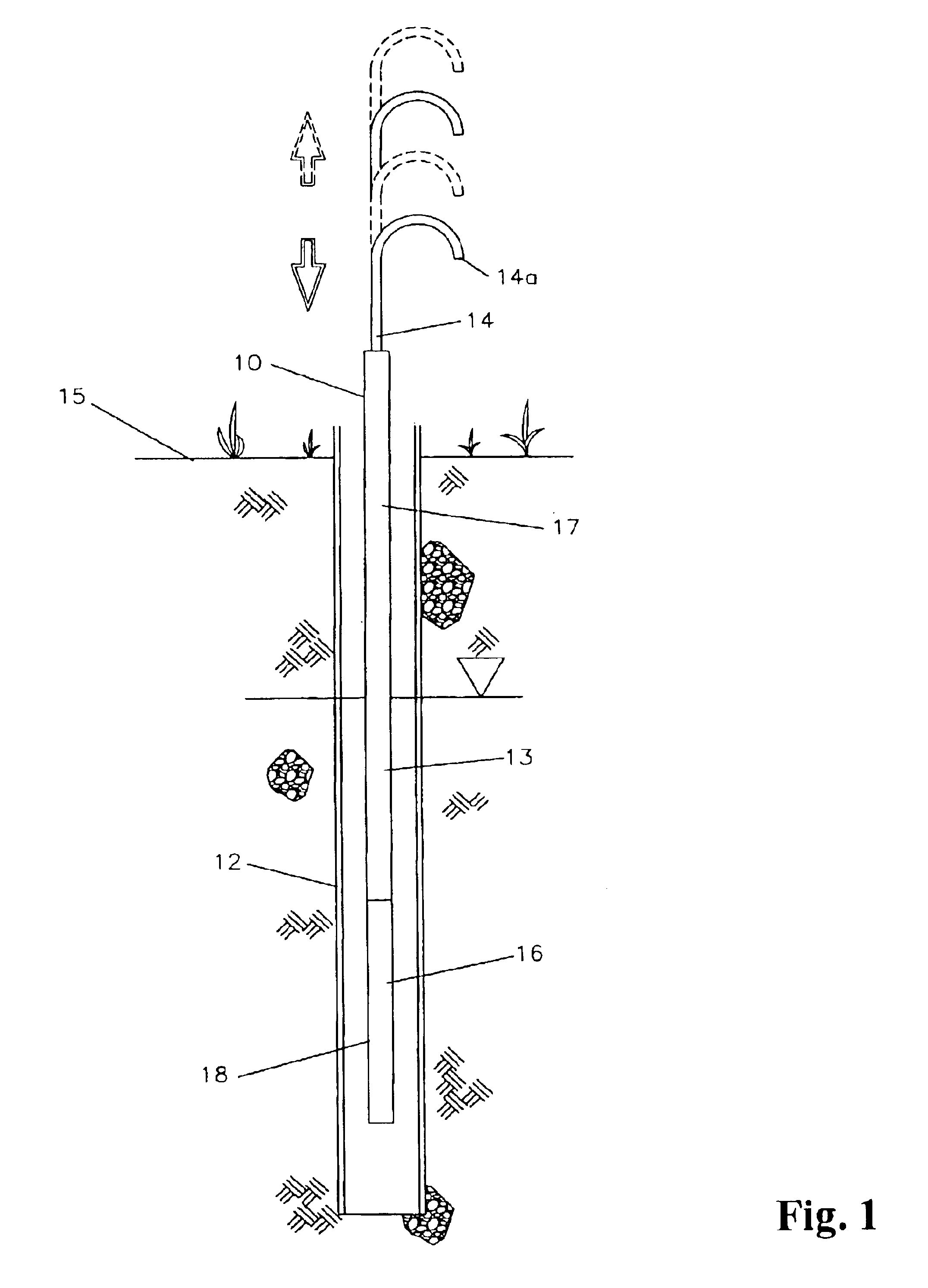
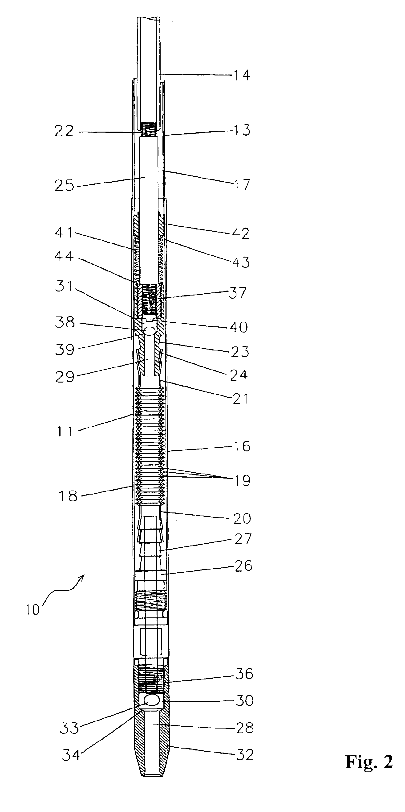
A mechanical bladder pump device 10 according to a preferred embodiment of the present invention will now be described with reference to FIGS. 1 to 5 of the accompanying drawings.

The mechanical bladder pump 10 of the present invention is a pumping device that uses a compressible bladder 11 to pump water or other fluids from one location to another by alternating between compression and expansion of the bladder 11. Fluid flow rate from the pump 10 can be controlled by the rate and amount of compression and expansion of the bladder 11. The bladder pump 10 is particularly suitable for collecting ground water samples from monitoring wells 12 and the like. When operated properly, the pump 10 can provide representative samples of groundwater with minimal, if any, disturbance of the water chemistry or quality.

The pump 10 includes an outer tubular member 13 having a longitudinal bore, and an inner tubular member 14 arranged concentrically within the bore of the outer tubular member 13. The ...


PUM


Abstract

A mechanical bladder pump is provided for collecting fluid samples from a well. The pump includes an outer tubular member having a longitudinal bore, and an inner tubular member arranged within the bore of the outer tubular member. The inner and outer tubular members are connected at their lower ends to a compressible bladder, and are arranged for oscillating movement relative to each other to expand and compress the bladder. The lower end of the bladder is open to an inlet passage, and the upper end of the bladder is open to an outlet passage. First and second check valves are provided to control the flow of fluid through the bladder during operation of the pump. A return spring is used to store energy during a tension stroke of the inner tubular member and to release energy during a compression stroke thereof. The pump provides highly representative samples of groundwater.

Description

BACKGROUND OF THE INVENTION1. Field of the InventionThe present invention relates generally to devices for pumping fluids from one location to another. In particular, the present invention relates to devices and methods for obtaining groundwater samples from monitoring wells.2. Description of the Related ArtCollection of representative groundwater samples from monitoring wells or other sampling devices has been the topic of much debate and research in the environmental field for more than twenty years. Not until the mid-1990s did the U.S. Environmental Protection Agency (“EPA”) establish a widely accepted methodology for obtaining representative groundwater samples. This accepted methodology is called the “low-flow minimal-draw down” procedure for sampling groundwater (EPA 1996). This sampling methodology was designed to have minimal impact on the water quality and chemistry of the sample collected, especially with respect to volatile organic contaminants (VOC) such as trichloroethe...

Claims


Application Information

Patent Timeline
Patent Type & Authority Patents(United States)
IPC IPC(8): F04B39/10F04B43/00F04B9/14E21BE21B27/00E21B43/00E21B43/12E21B49/00E21B49/08F04B19/00F04B43/08F04B43/10F04B53/00F04B53/12
CPCE21B43/127F04B43/084E21B49/086E21B49/084
Inventor MCCALL, WESLEYCHRISTY, THOMAS M.COOPER, DAVID
Owner KEJR
Why Eureka
Try Eureka