
Turbine part replacing apparatus

a technology for replacing parts and gas turbines, which is applied in the direction of lighting and heating equipment, combustion process, engine fuction, etc., can solve the problems of difficult to reach the combustors that are arranged in the lower half of the gas turbine, replacement systems are expensive, heavy, and take a lot of time, so as to improve the monitoring of the rotational position about a vertical position.

Active Publication Date: 2018-09-11
ANSALDO ENERGIA SWITZERLAND AG
View PDF10 Cites 2 Cited by
  • Summary
  • Abstract
  • Description
  • Claims
  • Application Information

AI Technical Summary

Benefits of technology

This patent describes a turbine part replacing apparatus that is particularly useful for replacing combustors and sequences in the lower half of a gas turbine. The apparatus is highly mobile, accurate, and lightweight, and it can support the heavy weight of typical combustors. It is stable and strong enough to minimize turbine downtime and reduce costs. Additionally, the arm of the apparatus can be disassembled for compact storage or shipping.

Problems solved by technology

This technique has, however, the draw back that it is difficult to reach combustors that are arranged in the lower half of the gas turbine.
These replacement systems are, however, heavy, bulky, expensive, and have to be attached to the casing which takes a lot of time.

Method used


Image

  • Turbine part replacing apparatus
  • Turbine part replacing apparatus
  • Turbine part replacing apparatus

Examples


Embodiment Construction

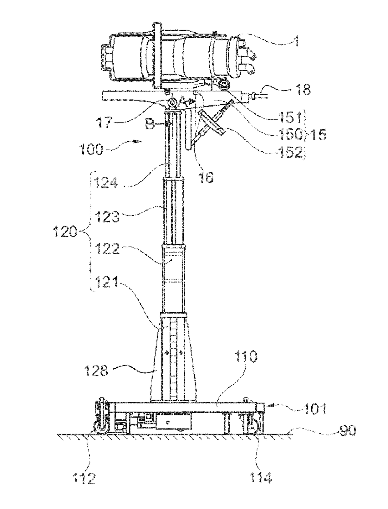
[0059]Some preferred embodiments are described in context of a replacement of a combustor 1. It is to be understood that also a sequential liner may be replaced.

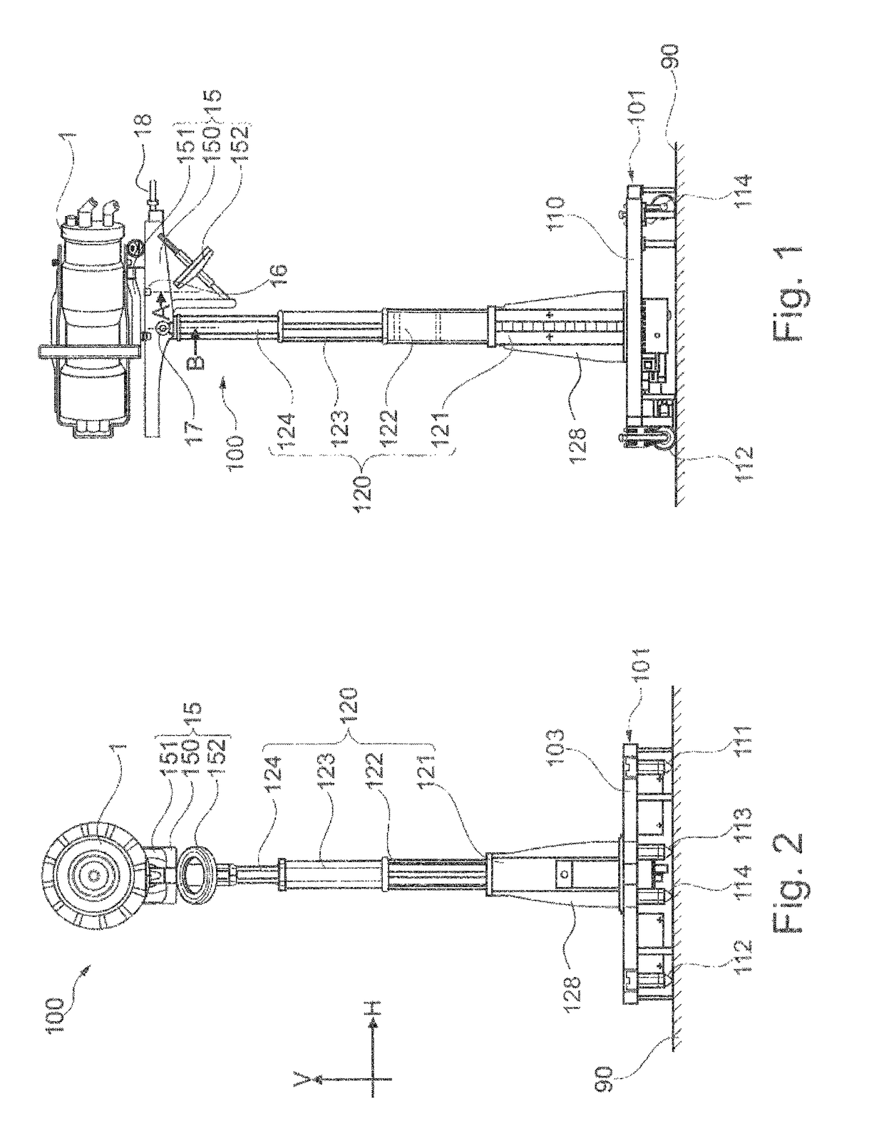
[0060]FIG. 1 shows, in a side view, a preferred embodiment of the turbine part replacement apparatus 100 loaded with the combustor 1. FIG. 2 shows a front view of said apparatus 100 according to FIG. 1.

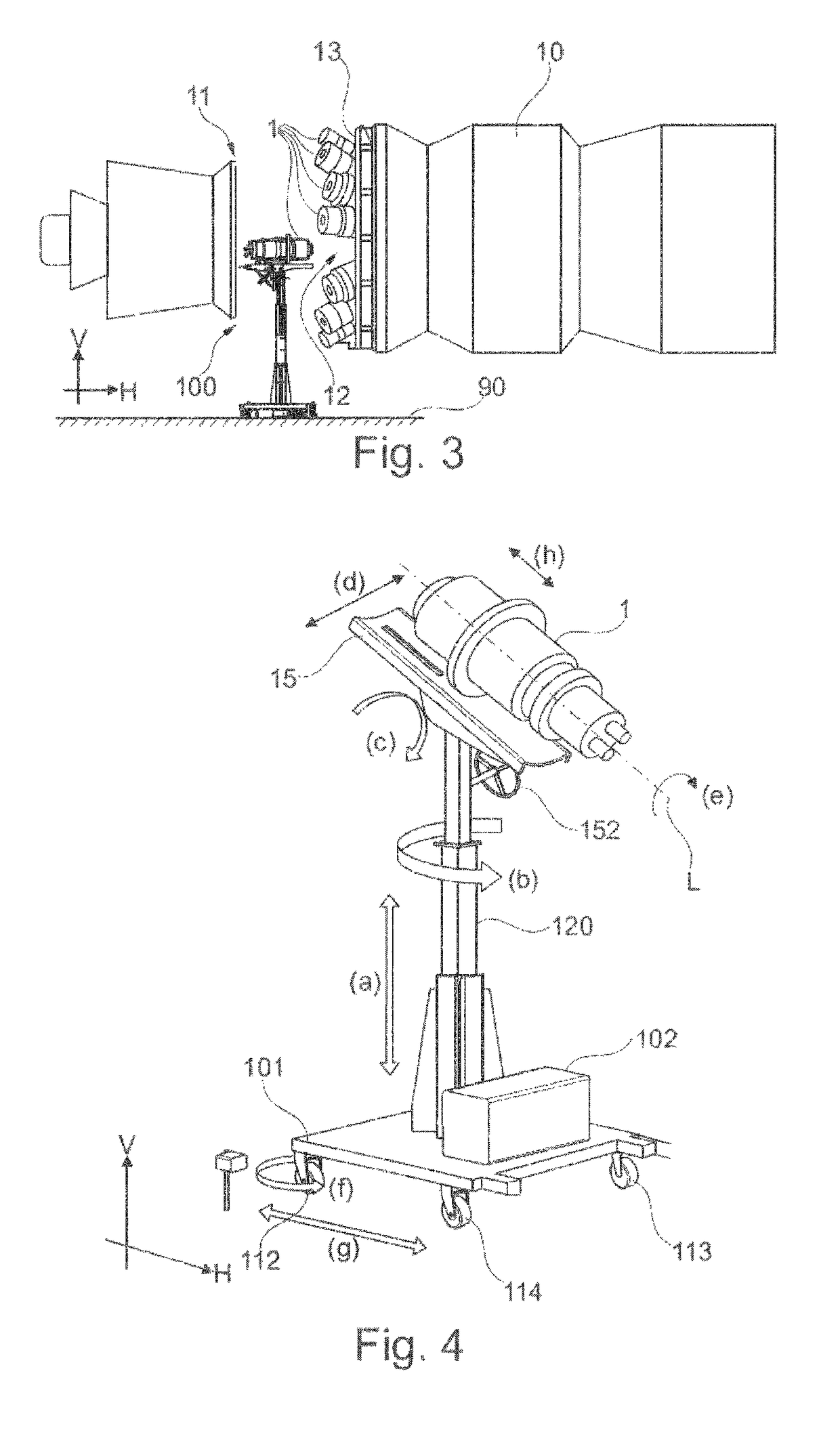
[0061]FIG. 3 shows the turbine part replacement apparatus 100 standing vertically on a horizontal ground 90 in a service zone 11 of an industrial gas turbine 10. The horizontal and vertical directions H, V are indicated by respective arrows. The turbine part replacement apparatus 100 is loaded with one combustor 1, combustor 1 having been removed from (or being delivered to) an empty mounting port 12.

[0062]Other combustors 1 are arranged next to the empty mounting port 12 and around the gas turbine 10 defining a plurality of combustor operation location. The mounted combustors 1 are flanged into an annular combustor assembly 1...


PUM


Abstract

A turbine part replacing apparatus for moving a combustor of an industrial gas turbine from and to a mounting port of the gas turbine is disclosed, the apparatus including a mobile frame with a moving mechanism for substantially horizontal translation motion on the ground, a vertically extendable arm attached to and extending from said mobile frame, and a carriage attached to the extendable arm such that the carriage may be moved vertically with respect to the mobile frame. Moreover, the turbine part replacing apparatus is adapted for receiving the combustor in the carriage and for vertically moving the received combustor by the extendable arm from and to the mounting port.

Description

TECHNICAL FIELD[0001]The present invention relates to a turbine part replacing apparatus usable for assembling or disassembling combustors and / or sequential liners or the like of a gas turbine. Moreover, the present invention relates to a method of replacing turbine parts of a gas turbine.PRIOR ART[0002]Large industrial gas turbines are typically equipped with a plurality of combustors that are fastened at equal intervals but individual orientations on an annular combustor assembly arranged around and attached to a casing of a gas turbine. The combustors are inserted into mounting ports and releasably flanged to the combustor assembly. As the combustors or other turbine parts like the sequential liner require regular maintenance, these parts have to be demounted and remounted from time to time.[0003]It is known to replace combustors of the gas turbine by means of a scaffold that is to be assembled around the gas turbine. A user may then operate an overhead crane to place a sling ove...

Claims


Application Information

Patent Timeline
Patent Type & Authority Patents(United States)
IPC IPC(8): F01D25/28B23P19/04F23R3/60
CPCB23P19/042F01D25/285F23R3/60F05D2260/30F05D2230/68F05D2260/02F05D2220/32F05D2230/60F05D2230/70F01D25/28F02C7/20
Inventor GERBER, HEINZARATORI, DAVIDESENG, DANIELSTENZ, VALENTIN
Owner ANSALDO ENERGIA SWITZERLAND AG
Learn More