Methods and apparatus for placing intradiscal devices

a technology of intradiscal devices and devices, applied in the field of spine surgery, can solve the problems of insufficient distraction of vertebrae, limited number of intradiscal devices that change size or shape, etc., and achieve the effect of convenient insertion of devices

Inactive Publication Date: 2005-04-12
ANOVA
View PDF5 Cites 238 Cited by
  • Summary
  • Abstract
  • Description
  • Claims
  • Application Information

AI Technical Summary

Benefits of technology

The present invention involves an osteotomy of a portion of a vertebral endplate and / or vertebral body to allow for easier insertion of a device that fits tightly into a disc space, especially the tallest portion(s) of the disc space. A different aspect of the invention resides in a mechanical device to hold the osteotomized portion of the vertebra against the vertebral body after the intradiscal device is placed. The device may be removed after the pieces of vertebra heal and fuse together.

Problems solved by technology

There are only a limited number of intradiscal devices that change size or shape within the disc space.
Third, surgeons can distract the vertebrae to insert the intradiscal device.
However, at times, the vertebrae cannot be distracted enough to allow the insertion of an intradiscal device that fits tightly within the central portion of the disc space and yet can be inserted past the periphery of the disc space.

Method used


Image

  • Methods and apparatus for placing intradiscal devices
  • Methods and apparatus for placing intradiscal devices
  • Methods and apparatus for placing intradiscal devices

Examples


Embodiment Construction

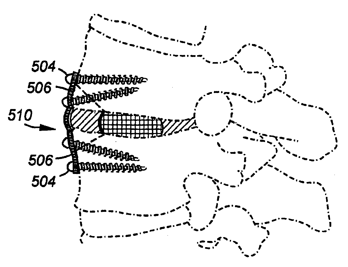
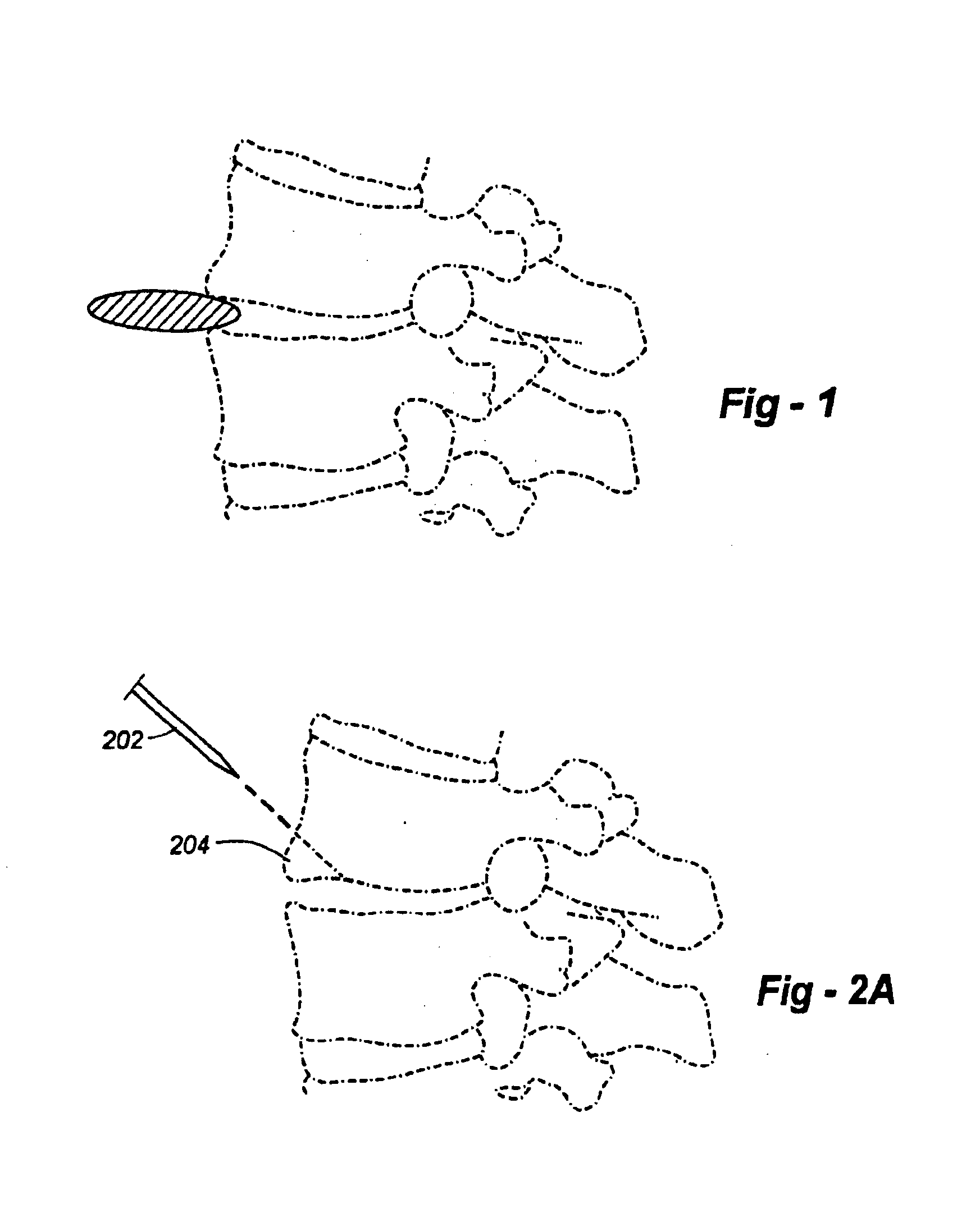
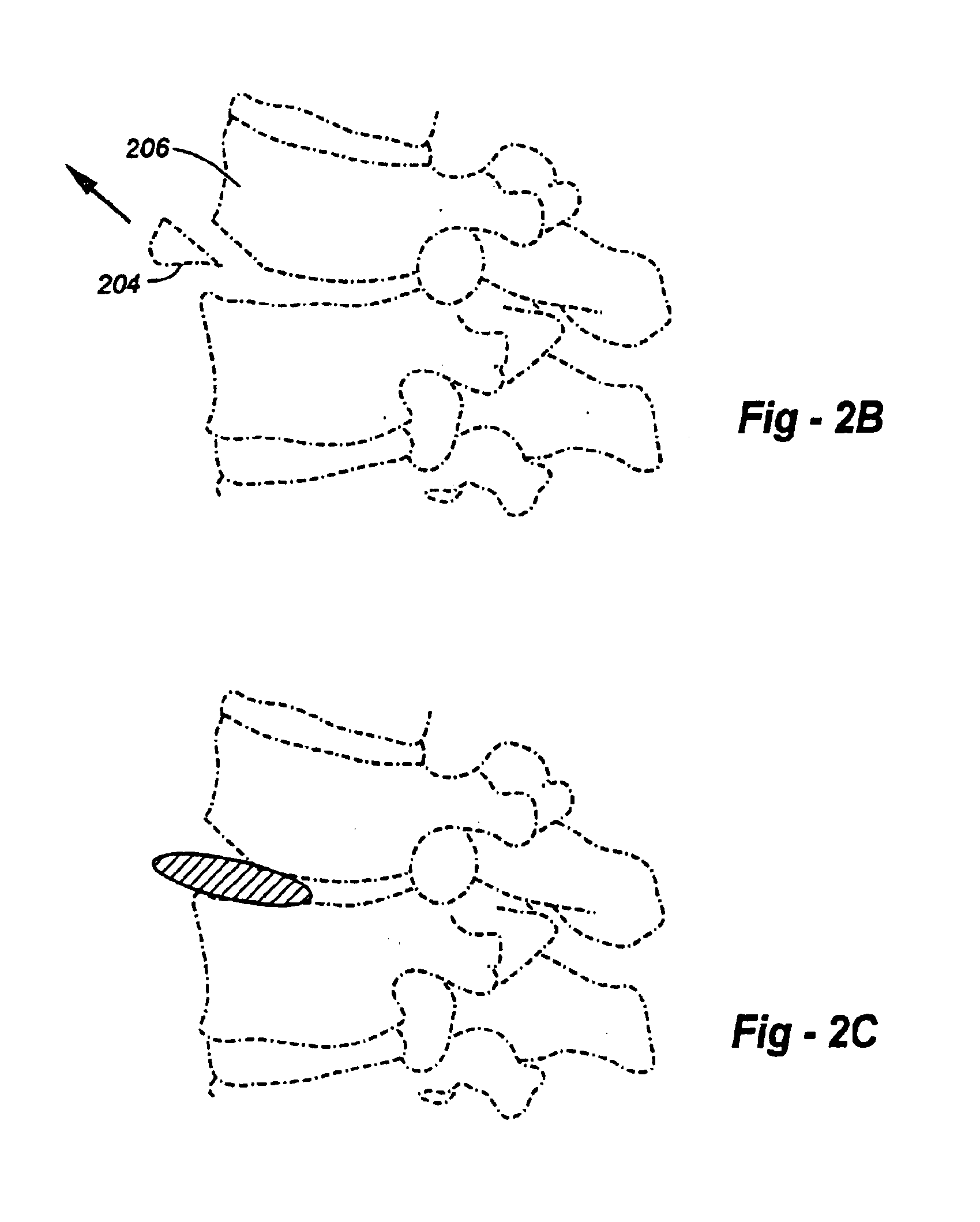
FIG. 2A is a side-view drawing illustrating an approach taken according to a method of the invention. In particular, a tool such as an osteotome 202 is used to remove or truncate a lower anterior portion of the upper vertebrae 206. FIG. 2B shows the portion removed from the vertebrae. FIG. 2C shows how, with the portion removed, the intradiscal device may be more easily inserted. FIG. 2D shows the intradiscal device in place in the intervertebral space. FIG. 2E shows the replacement of the osteotomized portion. Note that the piece of bone itself may be drilled and / or tapped if necessary, preferably before the osteotomy, to assist with reattachment.

FIG. 2F provides an anterior and lateral view showing the way in which the device is used to hold the osteotomized fragment. FIG. 2G is an anterior and lateral view of the preferred fragment-holding device, with the lateral or side view being shown in cross-section. As an alternative to a plate and fasteners, a cable system may be used to ...


PUM


Abstract

An osteotomy of a portion of a vertebral endplate and / or vertebral body allows for easier insertion of a device that fits tightly into a disc space. A different aspect of the invention resides in a mechanical device to hold the osteotomized portion of the vertebra against the vertebral body after the intradiscal device is placed. The device may be removed after the pieces of vertebra heal and fuse together.

Description

FIELD OF THE INVENTIONThis invention relates generally to spinal surgery and, in particular, to methods and apparatus for placing intradiscal devices.BACKGROUND OF THE INVENTIONIntradiscal devices are often shaped to fit within the natural concavities of the vertebral endplates that make up the disc space. As shown in FIG. 1, the entrance into the disc space is often narrower than the vertical space within the disc space. Currently surgeons have three choices when inserting devices that fit tight within the interior of the natural disc space. First, they can insert devices that change size or shape within the disc space. There are only a limited number of intradiscal devices that change size or shape within the disc space. Second, surgeons can remove a portion of the vertebrae endplate to allow the insertion of a device that fits tightly in the tallest portion of the disc space. Third, surgeons can distract the vertebrae to insert the intradiscal device. However, at times, the verte...

Claims


Application Information

Patent Timeline
Patent Type & Authority Patents(United States)
IPC IPC(8): A61B17/58A61B17/56A61F2/44A61F5/04A61BA61B17/15A61B17/17A61B17/70A61B17/80A61F2/00A61F2/28A61F2/30
CPCA61B17/15A61B17/1757A61B17/7059A61F2/442A61F2/30734A61B17/1728A61B17/8085A61F2/28A61F2310/00359A61F2/44A61F2002/30462A61F2002/4435A61F2220/0075
Inventor FERREE, BRET A.
Owner ANOVA
Why Eureka
Try Eureka