Floor covering of an elastically deformable material

a technology of elastic deformation and floor covering, applied in the field of floor covering, can solve the problems of damage that could occur in these thin areas of spaces under continuous high stress, and achieve the effect of good cushioning properties and long durability

Inactive Publication Date: 2005-04-12
WERKSITZ W MILEWSKI
View PDF15 Cites 62 Cited by
  • Summary
  • Abstract
  • Description
  • Claims
  • Application Information

AI Technical Summary

Benefits of technology

The invention comprises the essential idea of providing, in addition to the projections on the underside of the covering arranged without an overlapping area with the projections on the upper side, further projections which act as dynamic limiting means for pressing the covering down under high compressive loads. The height of these projections is less than the height of those projections on the underside of the floor covering on which it rests in an unstressed state, so that it does not start to act until a specific load (a preset pressure) is applied. They then increase, compared to a local load, with a characteristic line the rigidity of the covering, which can be adjusted via its height and shape as well as its grid size.
In a preferred embodiment, which is especially easy to clean and meets high requirements with respect to work safety and is esthetically pleasing, the first projections essentially have the shape of a spherical segment. In a further development of this embodiment, they are formed by a larger and a smaller spherical segment mounted on it. In this embodiment, the relative movement of the smaller spherical segment vis-à-vis the larger spherical segment produces an additional cushioning effect when loaded. Moreover, the more finely formed surface structure provides increased non-slip properties. These effects can also, moreover, be obtained in other combinations of a larger and a smaller basic moreover, be obtained in other combinations of a larger and a smaller basic geometric form, so that embodiments with basic geometric forms superimposed in this way can generally be considered advantageous.

Problems solved by technology

As a result, damage could occur in these thin areas of the spaces under continuous high stresses, in particular when there are alternating loads with relatively high frequency.
Damage of this type, at first in the form of microcracks, enable dust and other dirt to penetrate into the material where they can act abrasively and even amplify the material-damaging effects of the high mechanical stress.

Method used


Image

  • Floor covering of an elastically deformable material
  • Floor covering of an elastically deformable material
  • Floor covering of an elastically deformable material

Examples


Embodiment Construction

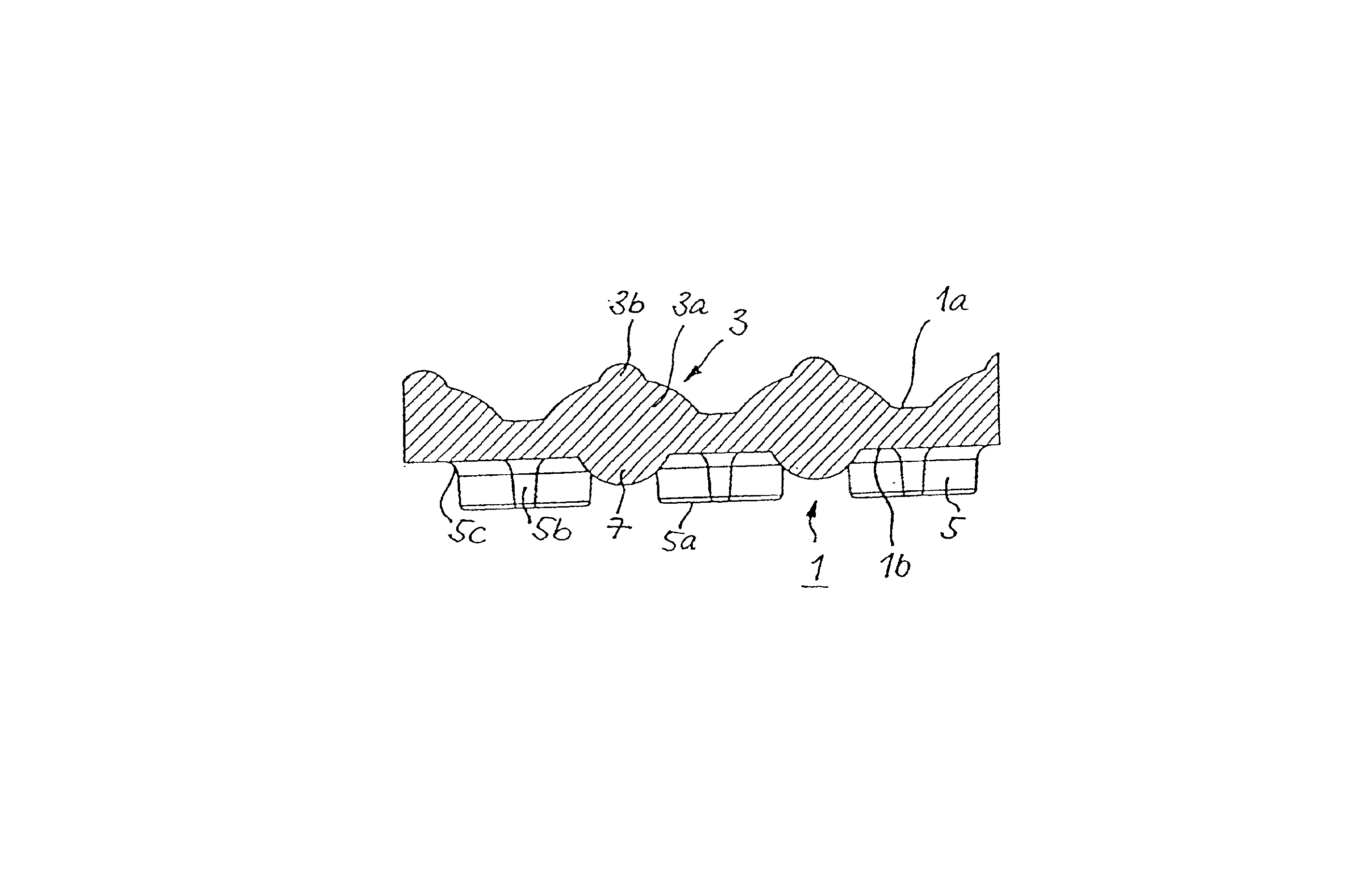
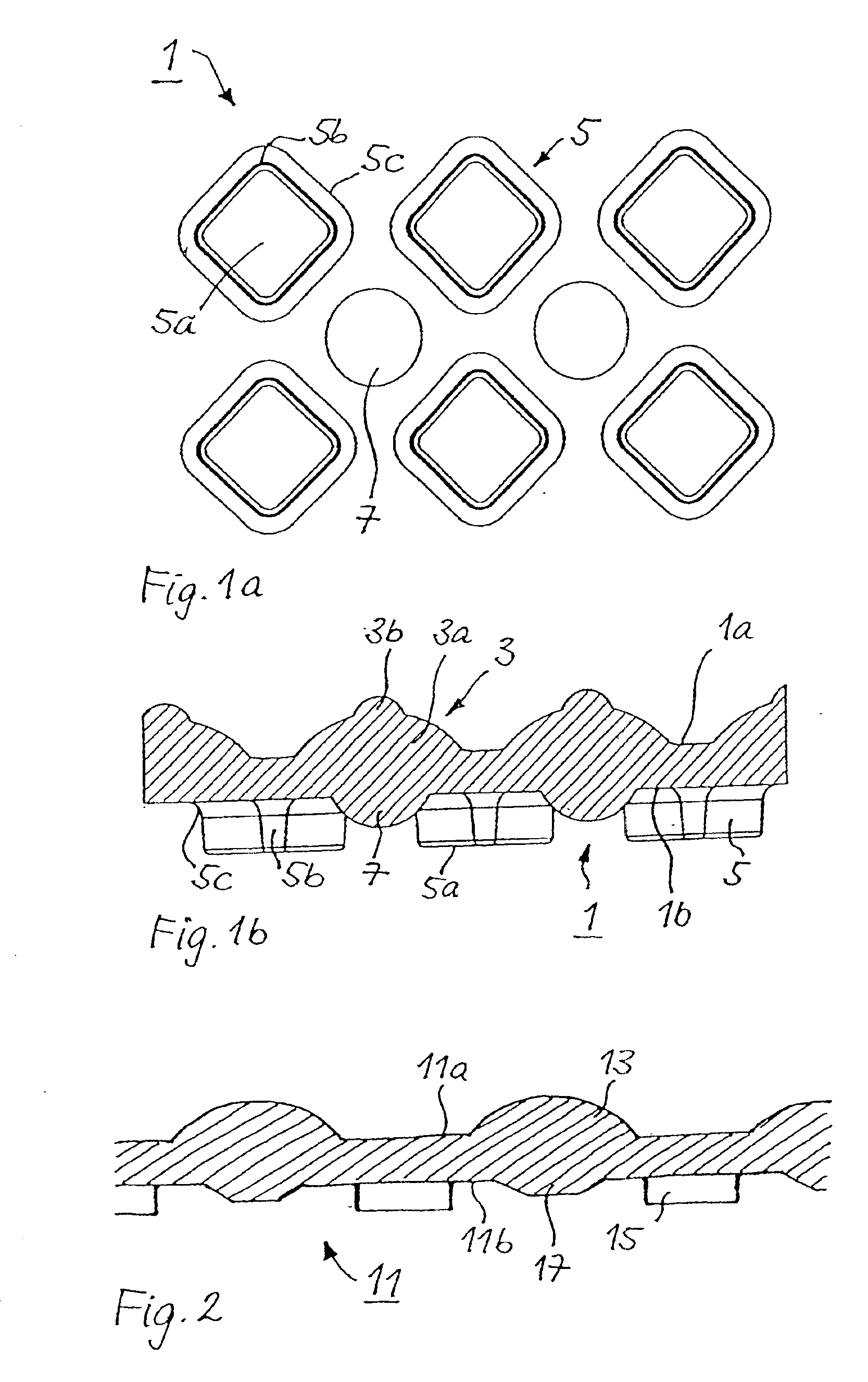
On the upper side 1a of the floor covering 1, it has first projections or elevations 3 whose form is composed of a first, larger spherical segment 3a and a second, substantially smaller spherical segment 3b, positioned on the highest point of the first spherical segment 3a. The height of the first spherical segment is about ⅕ to ¼ of its diameter on the covering plane. The height of the second spherical segment 3b is about ½ of the height of the first spherical segment 3a and the lateral extension of the second spherical segment corresponds to about ⅓ of that of the first spherical segment.

On the underside 1b of the floor covering 1, it carries first of all second projections or elevations 5 arranged in the interstices of the projections of the first projections 3 on the covering plane—i.e. essentially not overlapping with the first projections—and third projections 7 arranged between them and concentrically to the first projections 3 on the upper side 1a. (Only two of the third pro...


PUM

PropertyMeasurementUnit
heightaaaaaaaaaa
rigidityaaaaaaaaaa
shapeaaaaaaaaaa

Abstract

A floor covering (1) made of an elastically moldable material, in particular from a synthetic rubber, which is provided with a regular arrangement consisting of first projections (3) on the upper side (1a) and with a regular arrangement of second projections (5) on the underside (1b), the projections of the first projections and of the second projections not exhibiting any overlapping area on the plane of the covering and that, on the underside within the projections of the first projections, third projections (7) are provided in each case which have a smaller height vis-à-vis the second projections such that the floor covering only touches a floor with the second projections when it is in an unloaded state, however, when a preset load is exceeded locally, the third projections come in contact with the floor.

Description

BACKGROUND OF THE INVENTION1. Field of the InventionThe invention concerns a floor covering made of an elastically moldable material, in particular from a synthetic rubber, in accordance with the preamble of claim 1.2. Description of the Prior ArtFloor coverings of this type are known in various configurations and in practical use.Thus, a floor covering of the generic type is known from each of CH-A-419 547 or DK-B-170 603. According to these publications, the floor covering has a regular arrangement of elevations on the upper side and the underside, respectively, whose projections do not overlap one another, but are spaced slightly from one another.In these arrangements, considerable tensile stresses occur in the relatively thin area of the spaces between the projections on the top side and those on the underside when subjected to strong compressive loads, since, due to the compressive load, the underside of the covering is strongly pressed downward between the projections provided...

Claims


Application Information

Patent Timeline
Patent Type & Authority Patents(United States)
IPC IPC(8): A01K1/015A47G27/00A47G27/02B60N3/04E04F15/10
CPCA01K1/0157A47G27/0231B60N3/048E04F15/10Y10T428/24669Y10T428/24678Y10T428/24355Y10T428/24273
Inventor MILEWSKI, WOLFGANGHAFENECKER, SIMON
Owner WERKSITZ W MILEWSKI
Why Eureka
Try Eureka