Twist-on wire connector

a twist-on wire and connector technology, which is applied in the direction of cable junctions, connection end caps, coupling device connections, etc., can solve the problems of reducing the integrity of the connection between the wires affecting and affecting the use of solder or the like in the twist-on wire connector. , to achieve the effect of enhancing the current carrying capacity of the electrical wir

Inactive Publication Date: 2005-04-12
THE PATENT STORE
View PDF8 Cites 19 Cited by
  • Summary
  • Abstract
  • Description
  • Claims
  • Application Information

AI Technical Summary

Benefits of technology

Briefly the present inventions comprises an on-the-go twist-on wire connector for enhancing the current carrying capacity of the electrical wires contained therein with the housing having a closed end and an open end with a wire engaging coil located in the closed end of the housing for bringing a plurality of wires into surface-to-surface contact to provide a direct surface-to-surface electrical path for flow of electrical energy therebetween. Located in the closed end of twist-on wire connector is a pressure deformable wire adhereable electrical conducting medium with the conformable wire adhereable electrical conducting medium conformable around the plurality of wire ends as the plurality of wire ends are brought into surface-to-surface engagement with the conformable electrical conducting medium thereby forming an indirect current path between the wire ends while retaining the on-the-go ability of the twist-on wire connector to form an electrical connection solely through twisting action.

Problems solved by technology

The prior art process is time consuming because it involves two separate steps as well as the nuisance of having separate potting compounds and containers to hold the potting compound.
Under certain dynamic conditions, such as vibration and shock, or large temperature changes the wires in the twist-on wire connector can become loosened and thus lower the integrity of the connection between the wires in the twist on wire connectors by either increasing the electrical resistance or decreasing the contact area or both.
The use of solder or the like in twist on wire connectors is generally disliked not only because it requires additional steps and time but it also makes the connection permanent.
One of the ongoing difficulties with the field use of twist-on wire connectors is that in order not to have an inordinate number of different size twist-on wire connectors one size twist-on wire connector is used for multiple wires of different sizes.
That is, if the contact area between the ends of the electrical wires is relatively small a greater opportunity exists for exceeding the current carrying capacity of the wire junction and overheating the junction.

Method used


Image

  • Twist-on wire connector
  • Twist-on wire connector
  • Twist-on wire connector

Examples


Embodiment Construction

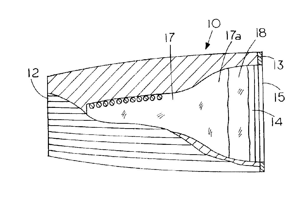
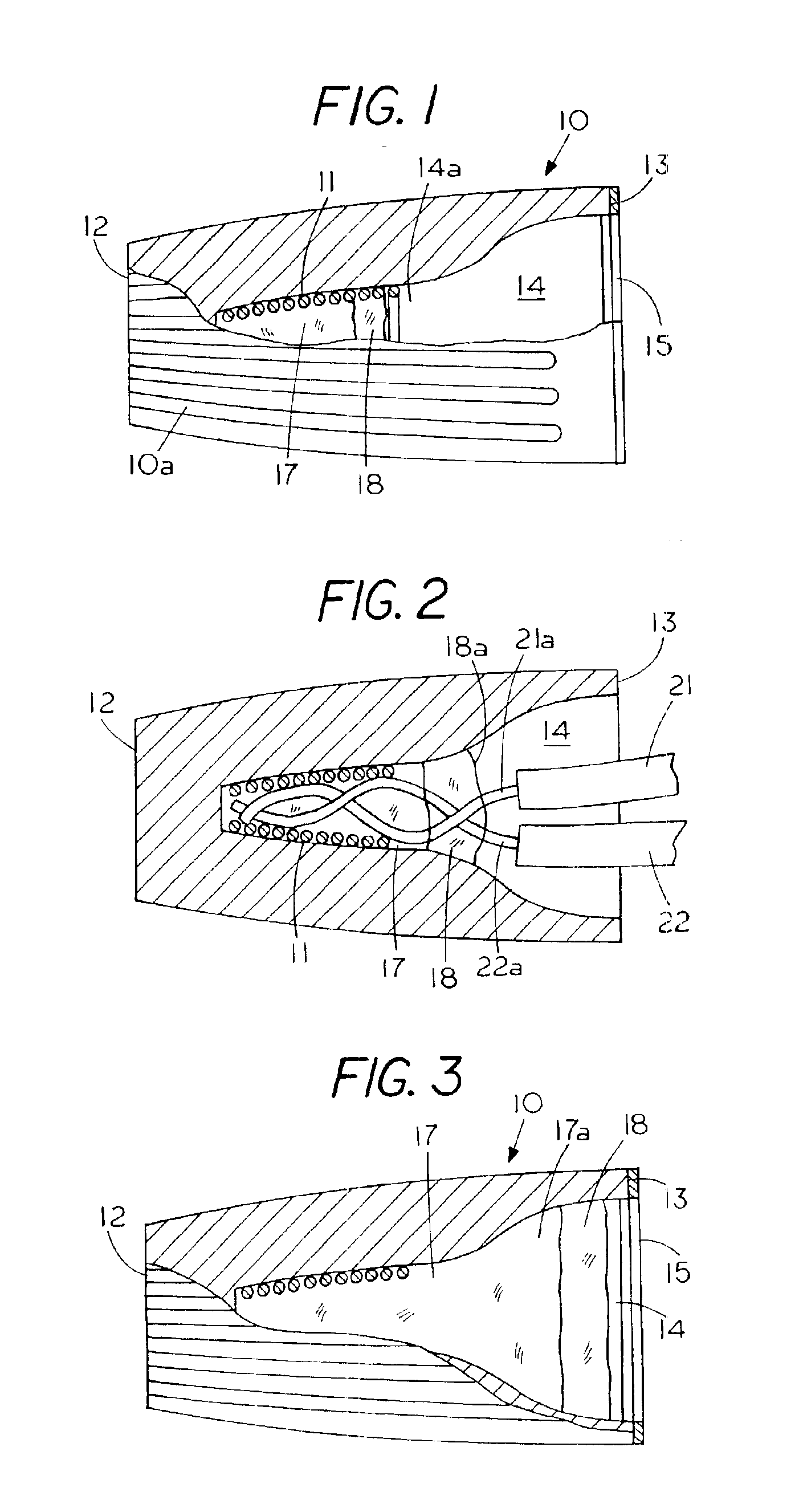
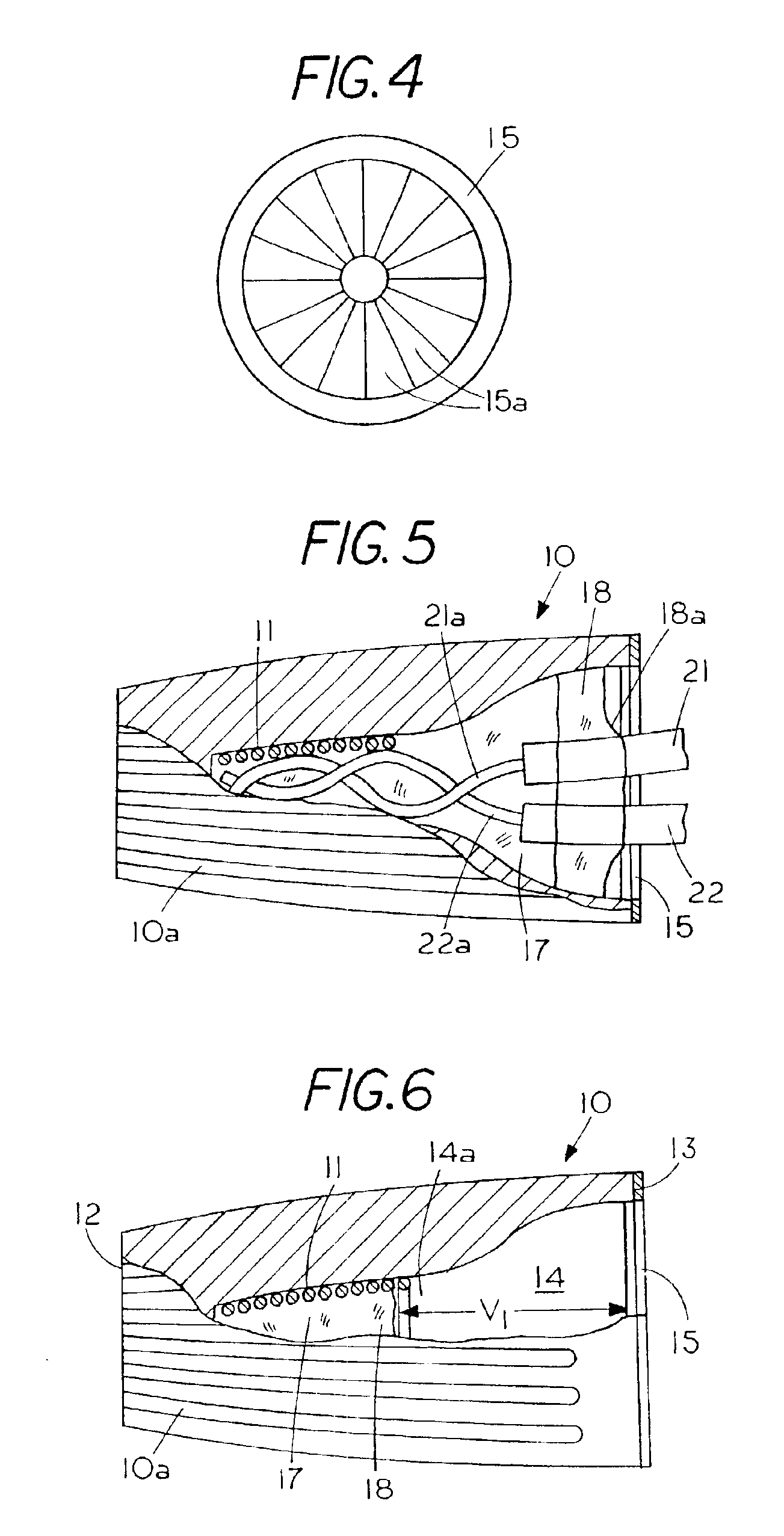
FIG. 1 is a partial cutaway view showing an on-the-go twist-on wire connector 10 having an exterior surface with a plurality of longitudinally extending finger engaging recesses 10a. Located inside a closed end 12 of wire connector 10 is a spiral thread 11 or wire engaging coil. Located on the opposite end of twist-on wire connector 10 is a wire penetrable end 13 for penetration of wires into a chamber 14 in twist-on wire connector 10. In the embodiment shown a wire penetrable cap 15 extends over the wire penetrable end 13 with cap 15 penetrable therethrough by flexing, punching or the like. On-the-go twist-on wire connectors are noted for there ease of use since the operator merely inserts a plurality of wires into the spiral thread of the wire connector and twists the wire connector to bring the wire ends into surface to surface contact with each other to create a current path from a surface contact area of one wire end to a surface contact area of another wire end without the nee...


PUM


Abstract

An on-the-go twist-on wire connector for enhancing the current carrying capacity of the electrical wires contained therein with the housing having a closed end and an open end with a wire engaging coil located in the closed end of the housing for bringing a plurality of wires into surface-to-surface contact to provide a direct surface-to-surface electrical path for flow of electrical energy therebetween. Located in the twist-on wire connector is a wire adhereable electrically conducting medium the adhereable electrical conducting medium is conformable around the plurality of wires as the plurality of wires are brought into surface-to-surface engagement with the conformable electrical conducting medium thereby forming an indirect current path between the ends of the plurality of wires while retaining the on-the-go ability of the twist-on wire connector to form the electrical connection solely through twisting action.

Description

FIELD OF THE INVENTIONThis invention relates generally to twist-on wire connectors and, more specifically, to an on-the-go twist-on wire connector having an electrically conducting medium for enhancing the current carrying capacity between the wire ends, which are located in the twist-on wire connector.CROSS REFERENCE TO RELATED APPLICATIONSNone.STATEMENT REGARDING FEDERALLY SPONSORED RESEARCH OR DEVELOPMENTNoneREFERENCE TO A MICROFICHE APPENDIXNoneBACKGROUND OF THE INVENTIONThe concept of on-the-go twist-on wire connectors for connecting the junction of two or more wires together by twisting a housing around the ends of wires is old in the art. Twist-on wire connectors are well known in the art and generally comprise an outer open end housing with a tapered threaded interior, such as a spiral thread, to permit a user to insert wires into the tapered threaded interior. To use a twist-on wire connector, the user inserts the ends of electrical wires into the spiral threaded cavity on ...

Claims


Application Information

Patent Timeline
Patent Type & Authority Patents(United States)
IPC IPC(8): H01R13/52H01R4/22H01R4/10H01R4/00H01R4/12H01R4/70H01R13/514
CPCH01R4/12H01R13/5216H01R4/22H01R13/514
Inventor KING, JR., LLOYD HERBERT
Owner THE PATENT STORE
Why Eureka
Try Eureka