Vacuum circuit breaker having a high current-carrying capacity

a vacuum circuit breaker and high current-carrying technology, applied in the field of circuit breaker technology, can solve the problems of failure, need maintenance, and active blower, and achieve the effects of effective thermal contact, simplified production of vacuum switching chamber with heat pipe, and efficient cooling

Inactive Publication Date: 2008-01-03
ABB RES LTD
View PDF3 Cites 19 Cited by
  • Summary
  • Abstract
  • Description
  • Claims
  • Application Information

AI Technical Summary

Benefits of technology

[0013] Owing to the provision of the heat pipe, efficient dissipation of heat is possible, with the result that a higher current-carrying capacity is achieved.
[0034] Advantageously, in particular if only one heat pipe is provided, the evaporator is arranged close to the center of the vacuum switching chamber. As a result, particularly efficient cooling of the vacuum switching chamber is achieved.

Problems solved by technology

One problem with such an arrangement is the fact that the blower is active, i.e. needs to be driven.
It requires maintenance and may fail.

Method used


Image

  • Vacuum circuit breaker having a high current-carrying capacity
  • Vacuum circuit breaker having a high current-carrying capacity
  • Vacuum circuit breaker having a high current-carrying capacity

Examples


Embodiment Construction

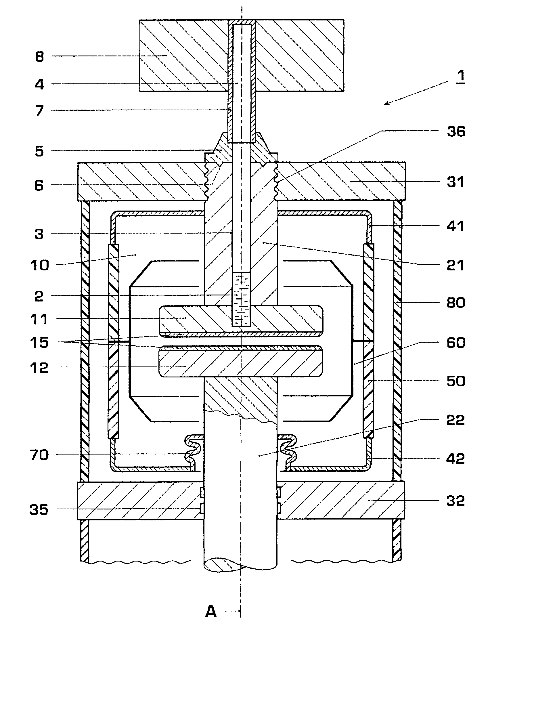
[0044]FIG. 1 shows, schematically and sectioned, a vacuum switching chamber in the open state having a rigid heat pipe in accordance with the prior art.

[0045] The vacuum switching chamber is designed to be substantially rotationally symmetrical with an axis A and contains two contact pieces 11 and 12. The contact piece 12 can be moved by means of a drive (not illustrated). The contact piece 11 is stationary. The contact pieces 11 and 12 are fixed to contact stems 21 and 22, respectively.

[0046] The vacuum switching chamber further has an insulating body 50, typically consisting of ceramic, which is hollow-cylindrical and is sealed at its ends by in each case one cover 41; 42. The enclosed volume 10 is evacuated. The movable contact stem 22 is fixed to the cover 42 with a folding bellows 70 interposed. The stationary contact stem 21 is fixed to the cover 41. A shield 60 prevents the insulating body 50 from losing its insulating properties and becoming electrically conductive by bein...


PUM


Abstract

The vacuum switching chamber has two contact pieces and is provided with at least one heat pipe for dissipating heat. The heat pipe contains a working medium for dissipating the heat by evaporating the working medium in a section, referred to as the evaporator, of the heat pipe and condensing the working medium in a section, referred to as the condenser, of the heat pipe. Advantageously, the evaporator is in close thermal contact with at least one contact piece, and, in particular, at least part of the evaporator is integrated in the first contact piece or the second contact piece. Advantageously, the condenser has a cooling rib arrangement.

Description

RELATED APPLICATIONS [0001] This application claims priority under 35 U.S.C. §119 to EP Application 04405786.7 filed in Europe on Dec. 20, 2004, and as a continuation application under 35 U.S.C. §120 to PCT / CH2005 / 000748 filed as an International Application on Dec. 14, 2005, designating the U.S., the entire contents of which are hereby incorporated by reference in their entireties.TECHNICAL FIELD [0002] The invention relates to the field of circuit breaker technology, in particular high-voltage and medium-voltage circuit breaker technology and particularly to vacuum switching chambers. It relates to a vacuum switching chamber and to a method for cooling a vacuum switching chamber in accordance with the preamble of the independent patent claims. BACKGROUND INFORMATION [0003] Vacuum switching chambers are known from the prior art which are forcibly cooled so as to increase the current-carrying capacity. The vacuum switching chamber is arranged in an insulating tube, through which air...

Claims


Application Information

Patent Timeline
Patent Type & Authority Applications(United States)
IPC IPC(8): H01H33/664F28D15/02
CPCH01H1/62H01H2033/6613H01H2009/523H01H33/6606
Inventor STEFFENS, ALEXANDERLAKNER, MARTINKIEFER, JOCHENCHARTOUNI, DANIELGENTSCH, DIETMAR
Owner ABB RES LTD
Why Eureka
Try Eureka