Inductor current emulation circuit for switching power supply

a current emulation circuit and switching power supply technology, applied in the direction of dc-dc conversion, power conversion systems, instruments, etc., can solve the problems of power dissipation, adds cost to the smp, and also has drawbacks in the approach

Active Publication Date: 2005-04-12
ANALOG DEVICES INC
View PDF2 Cites 70 Cited by
  • Summary
  • Abstract
  • Description
  • Claims
  • Application Information

AI Technical Summary

Benefits of technology

An inductor current emulation circuit for an SMPS is presented. The invention provides accurate inductor curre...

Problems solved by technology

However, the use of a suitable current-sensing resistor adds cost to the SMPS, and power is dissipated as heat in the resistor.
This approach also has drawbacks, however.
This can cause the voltage across the resistor to become distorted with respect to the sensed current.
Analog and digital filtering techniques have been used to mitigate these problems, but these increase cost and complexity.
Unfortunately, this emulation method has several problems.
The equivalent series resistance of the inductor may not be well-controlled or specified, and can vary substantially over tem...

Method used


Image

  • Inductor current emulation circuit for switching power supply
  • Inductor current emulation circuit for switching power supply
  • Inductor current emulation circuit for switching power supply

Examples


Embodiment Construction

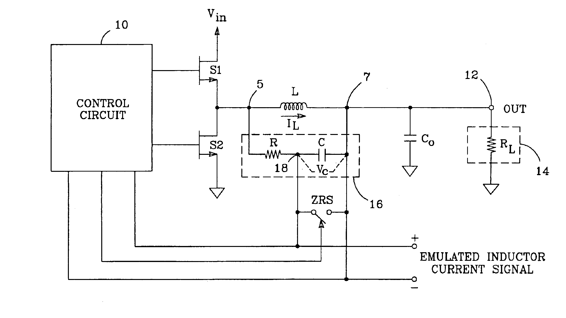
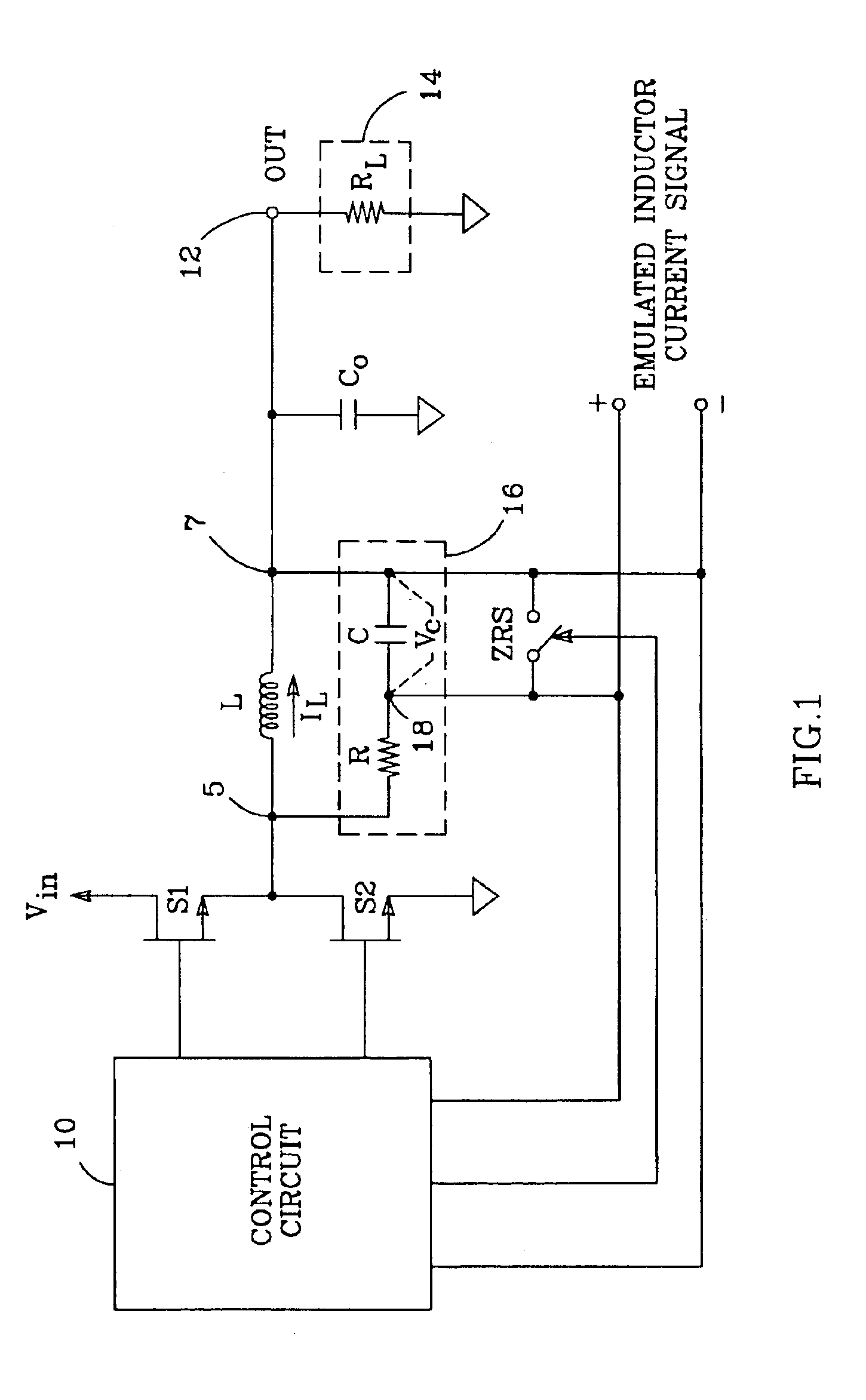
The basic principles of the invention are illustrated in FIG. 1. A typical SMPS includes a pair of output switches S1 and S2, an output inductor L, and a filter capacitor Co. Inductor L is connected to a “switched-voltage” terminal 5 which is connected to switches S1 and S2, and to a “capacitively-filtered terminal 7 which is connected to filter capacitor Co. A control circuit 10 operates switches S1 and S2 to alternately conduct current to and from inductor L to create a desired output voltage at an output terminal 12; a load 14, represented in FIG. 1 with a load resistor RL, is driven by the SMPS. The invention requires that the SMPS be arranged such that the current IL in inductor L goes to zero at least once per switching cycle under static operating conditions, as with, for example, a discontinuous-inductor-current SMPS, or a continuous-bipolar-inductor-current SMPS. Note that, though a buck-type converter is shown and described herein, the invention is applicable to any SMPS w...


PUM


Abstract

An inductor current emulation circuit for a switched-mode power supply (SMPS) which is arranged such that its inductor current (IL) goes to zero at least once per switching cycle. The emulation circuit includes an RC integrator connected in parallel across the inductor, and a zero reset switch (ZRS) connected in parallel across the integrator's capacitor. A control circuit operates the ZRS such that it is opened when IL is non-zero, and is closed for a least a portion of the time during each switching cycle when IL is zero such that the capacitor is substantially discharged. In this way, the ZRS essentially recalibrates the emulation circuit when IL is zero. When so arranged, the voltage (VC) across the capacitor emulates IL. The invention may be implemented with either a discontinuous-inductor-current SMPS, or a continuous-bipolar-inductor-current SMPS.

Description

BACKGROUND OF THE INVENTION1. Field of the InventionThis invention relates to the field of switched-mode power supplies (SMPS), and particularly to methods of determining the current flowing in the inductor of an SMPS.2. Description of the Related ArtSwitched-mode power supplies (SMPS), which switch voltage to and from an inductor to effect current through it (e.g., to provide a regulated voltage output), often use information about the current (IL) flowing in the inductor to control the switching. One way of sensing IL is by adding a current-sensing resistor in series with the inductor; the voltage across the resistor varies with IL. However, the use of a suitable current-sensing resistor adds cost to the SMPS, and power is dissipated as heat in the resistor.Minimizing the size of the current-sensing resistor lessens these problems: a lower resistance reduces power dissipation, allowing the use of a physically smaller resistor which lowers cost. This approach also has drawbacks, ho...

Claims


Application Information

Patent Timeline
IPC IPC(8): G05F1/10G05F1/44H02M3/156
CPCH02M3/156H02M2001/0009H02M1/0009
Inventor ERISMAN, BRIAN P.REDL, RICHARD
Owner ANALOG DEVICES INC
Why Eureka
Try Eureka