High frequency oscillator with vertical resonator

a dielectric resonator and high frequency oscillator technology, applied in the direction of resonators, oscillators, electrical equipment, etc., can solve the problems of difficult balance of horizontal resonators and general inadequate performan

Inactive Publication Date: 2005-04-12
ROBERT BOSCH GMBH
View PDF2 Cites 1 Cited by
  • Summary
  • Abstract
  • Description
  • Claims
  • Application Information

AI Technical Summary

Benefits of technology

It is an object of the present invention to provide an oscillator with a vertical dielectric resonator, which is compactly formed and is equalized with simple means.
The inventive oscillator, in contrast to the known oscillators, offers the advantages that a simple mounting by means of the flattened portion is possible, that by means of the selection of an elliptical shape of the resonator, a small height can be realized, that the symmetrical or asymmetrical hole (bore) of the resonator permits material savings, in particular, tantalum, and that the resonator is operated in higher modes.

Problems solved by technology

Horizontal resonators are difficult to balance and have a generally inadequate performance.

Method used


Image

  • High frequency oscillator with vertical resonator
  • High frequency oscillator with vertical resonator
  • High frequency oscillator with vertical resonator

Examples


Embodiment Construction

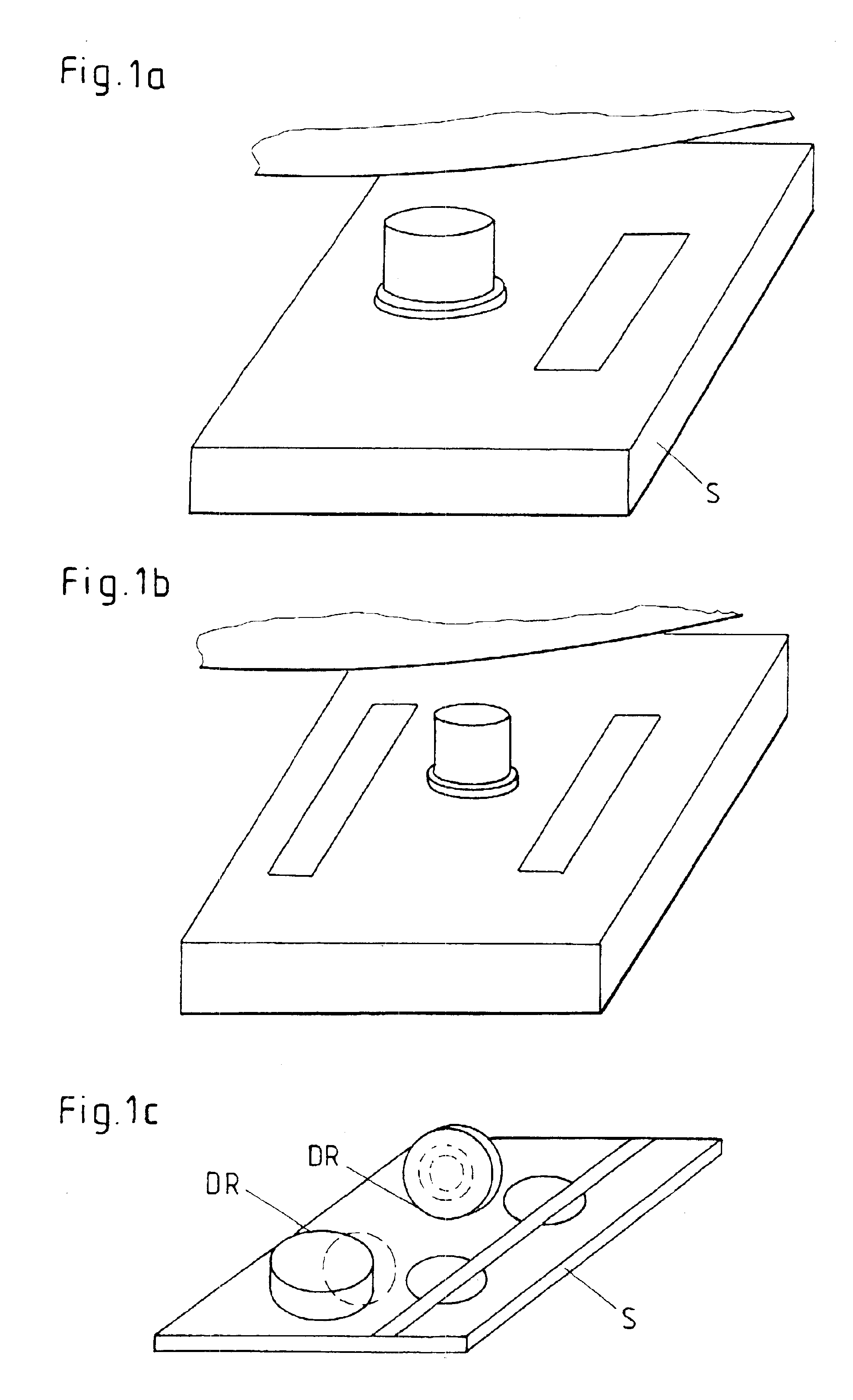
In FIG. 1, known forms of resonators DR are illustrated.

For reflecting and transmitting oscillators, the forms corresponding to the representation in FIGS. 1a and 1b are used (classic methods in band stop and band pass methods).

In FIG. 1c, the classic and the proposed form of the resonators according to U.S. Pat. No. 5,701,104 are shown.

Calculations on horizontal resonators have shown that in addition to know TM021 modi known from the state of the art, a multitude of other possibilities of stimulation are provided. With a stimulation of the TE310 or TE410 modi, the field intensity reaches a maximum sized in a ring in the region of the outer edge and in the center, null, that means, the center is field-free.

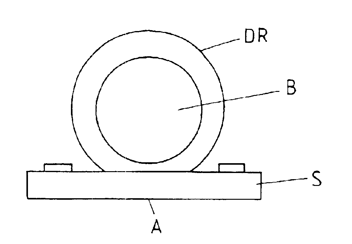
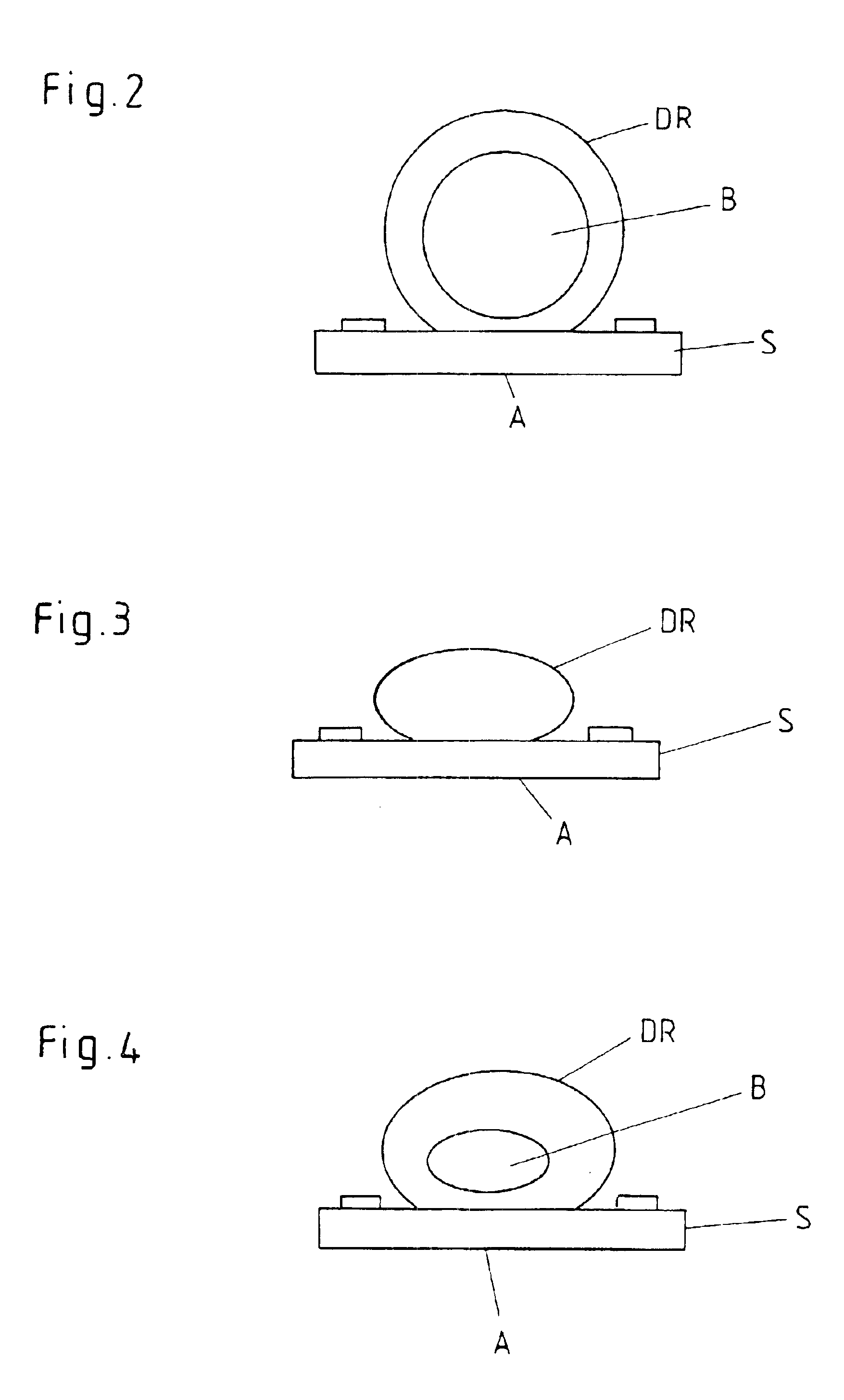
One embodiment of the vertical resonator DR in a hoop form is shown in FIGS. 2 through 4.

This structure makes possible the use of dielectric with high dielectric constants (er=30 to 80), in addition to material savings, so that a compact structure can be achieved.

In FIG. 2, the ho...


PUM


Abstract

A high frequency oscillator includes a dielectric, cylindrical resonator (DR) as a frequency-determining element. The dielectric resonator (DR) is arranged vertically on a substrate (S) on its shell. The resonator (DR) is formed as a hoop, such that the field intensity in the region of the outer edge of the hoop is at a maximum and in the center, is null, that is field-free.

Description

BACKGROUND OF THE INVENTIONThe present application relates to a high frequency oscillator with a vertical, dielectric resonator as a frequency-determining component.It is-known to use horizontal dielectric resonators (DR) as frequency-determining components for microwave oscillators. For increasing the performance, often these are placed on a ring-shaped spacer made from materials with low dielectric constants and operate in H110-mode. As oscillators, reflection types or transmission types (feedback types) are used (D. Kajfez and P. Guillon eds.: Dielectric Resonators, Artech House books (1986); I. Bahl et al: Microwave Solid State Circuit Design, Wiley (1988) pp. 426-482).Horizontal resonators are difficult to balance and have a generally inadequate performance.From U.S. Pat. No. 5,701,104, the use of vertical resonators is known. These are operation in rotationally symmetrical modes, for example, TM21+delta. By means of the other types of coupling, an increased performance can be ...

Claims


Application Information

Patent Timeline
IPC IPC(8): H01P1/203H01P1/20H03B5/18
CPCH03B5/187H01P1/20309
Inventor VOIGTLAENDER, KLAUS
Owner ROBERT BOSCH GMBH
Why Eureka
Try Eureka