Electronically-controlled locker system

Inactive Publication Date: 2005-04-12
SOURCE PTI OPCO LLC +3
View PDF24 Cites 162 Cited by
  • Summary
  • Abstract
  • Description
  • Claims
  • Application Information

AI Technical Summary

Benefits of technology

FIG. 14 is an alternative electronically-controlled lock...

Problems solved by technology

However, in view of the above, there still remains a need for an electronically-controlled locker system that provides system administrators, especially sc...

Method used


Image

  • Electronically-controlled locker system
  • Electronically-controlled locker system
  • Electronically-controlled locker system

Examples


Embodiment Construction

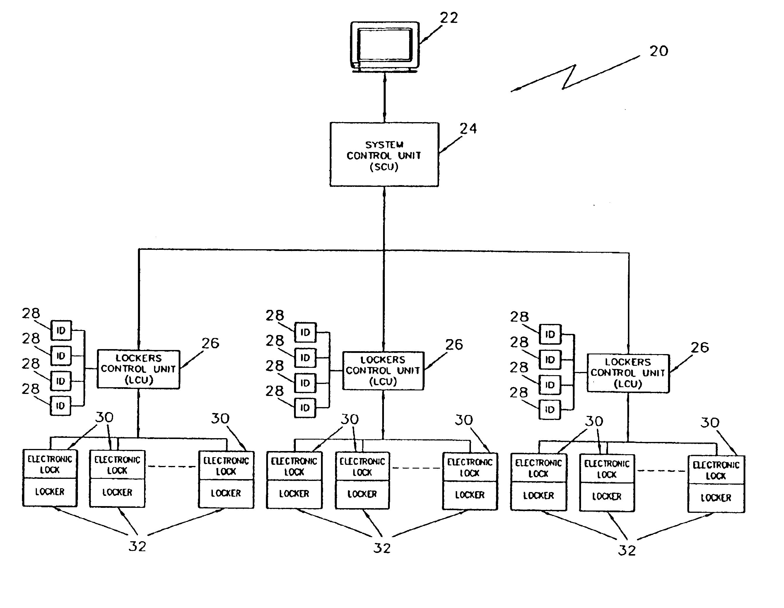
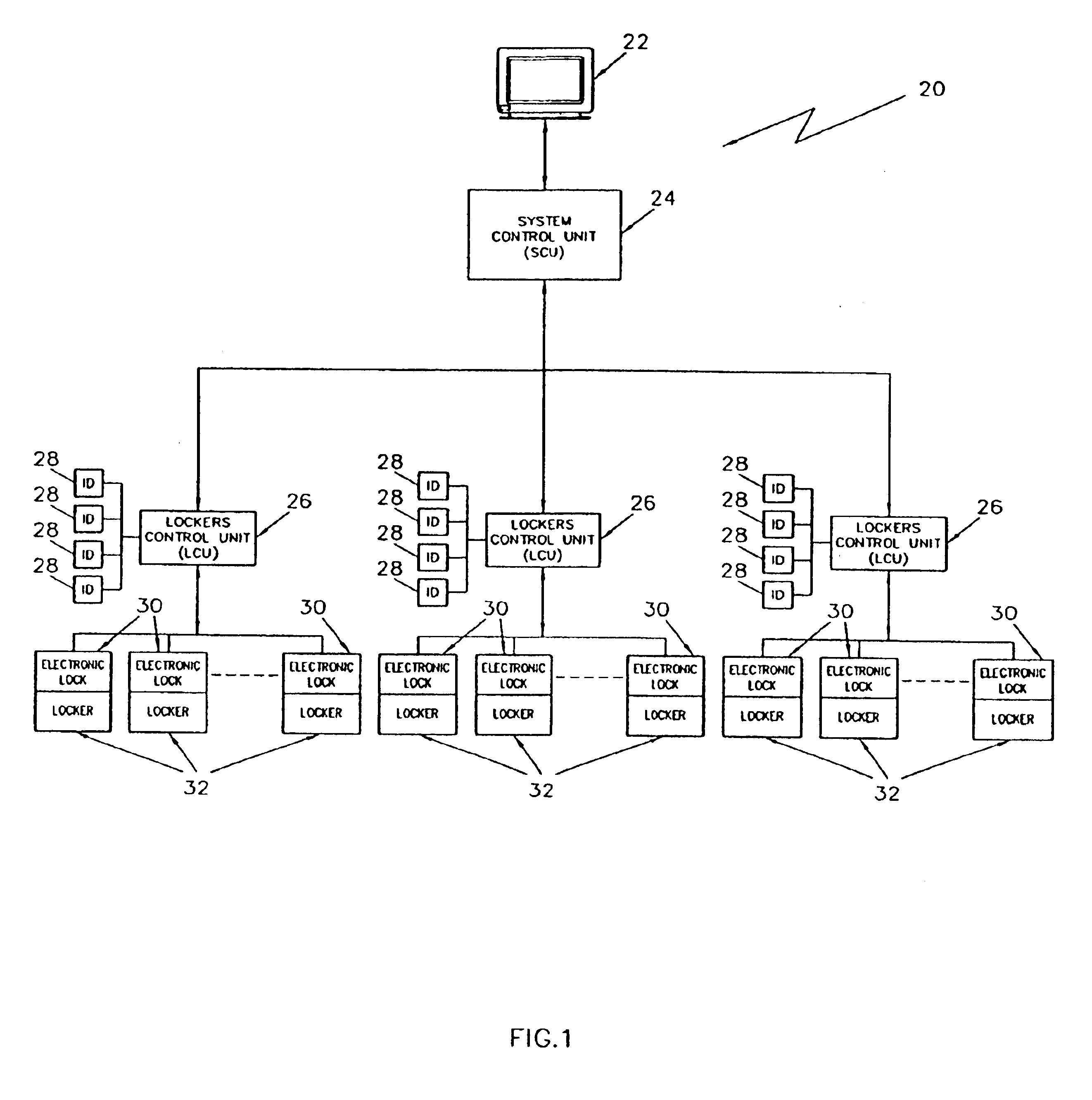
Referring now in detail to the various figures of the drawing wherein like reference characters refer to like parts, there is shown at 20 in FIG. 1 an electronically-controlled locker system (hereinafter the “ECLS”) of the present invention. The ECLS 20 basically comprises a system administrator computer 22 (SAC, e.g., a personal computer having Windows-95 capability, Apple Macintosh capability, etc.), a system control unit (SCU) 24, a plurality of locker control units (LCUs) 26, a plurality of input devices (IDs) 28 that control access to another plurality of electronic locks 30 for respective lockers 32. Although the ECLS 20 is primarily designed for use in schools, the ECLS 20 can be easily adapted for use in other environments such as fitness clubs, employee lockers, workplaces, airports, resorts, shopping malls, law enforcement, etc., or any environment where it is desirable to control access to banks of lockers from a remote location. The ECLS 20 provides the ability to search...


PUM


Abstract

An electronically-controlled locker system that utilizes distributing processing to control access to, and assignment of, a plurality of lockers in a school, workplace, fitness center, etc. The system uses a plurality of locker control units that control access to a corresponding set of lockers based on user inputs and on user/locker authorization data that is provided from a central administrator workstation. This administrator workstation communicates with a system control unit that is in communication with every locker control unit and which allows cross-communication between locker control units.

Description

FIELD OF THE INVENTIONThe invention generally relates to electronically-controlled lockers, and more particularly, to a system for remotely-controlling access to a plurality of lockers such as those found in schools, fitness clubs, employee lockers, airports, resorts, shopping malls, and law enforcement.BACKGROUND OF INVENTIONThere are now increased security needs in schools and commercial buildings. There is also a high degree of computer literacy among educators, and property managers. Furthermore, there is increasing use of ID cards, coded with intelligence for recording of activities and the trend now is towards large school construction budgets with more funds being allocated to security issues. It is now common place for new construction to include extensive pre-wiring for data transmission systems. As a result, there remains a need for an electronically controlled locker system for use, especially in schools. For example, school administrators can spend up to 240 man hours se...

Claims


Application Information

Patent Timeline
IPC IPC(8): E05B47/02G07C9/00G07F17/12G07F7/10G07F17/10E05B15/00E05B17/00E05B15/02
CPCE05B47/026G07F17/12G06Q20/40145G07C9/00103G07F7/1008G06Q20/341E05B17/0037E05B2015/0235G07C9/27
Inventor BOOTH, KEVIN E.POPOLOW, HARRY N.FORD, RICHARD R.JOHNSON, EDWARD E.LOFTIN, JON S.OSBORNE, LANCE C.JOHNSON, DAVID W.
Owner SOURCE PTI OPCO LLC
Why Eureka
Try Eureka