Apparatus for and method of variable bit rate video coding

Inactive Publication Date: 2005-04-12
NEC CORP
View PDF23 Cites 24 Cited by
  • Summary
  • Abstract
  • Description
  • Claims
  • Application Information

AI Technical Summary

Benefits of technology

The present invention has been made in view of the above problems, and it has an object of providing a single pass variable bit rate coding system, which permits r

Problems solved by technology

Therefore, it is impossible to encode in real time processing.
However, the above signal pass variable bit rate coding systems have a problem that a series of coding processes may result in deterioration of the image quality.
This means that preference is given to bit rate control in a fixed time perio

Method used


Image

  • Apparatus for and method of variable bit rate video coding
  • Apparatus for and method of variable bit rate video coding
  • Apparatus for and method of variable bit rate video coding

Examples


Example

Preferred embodiments of the present invention will now be described with reference to the drawings.

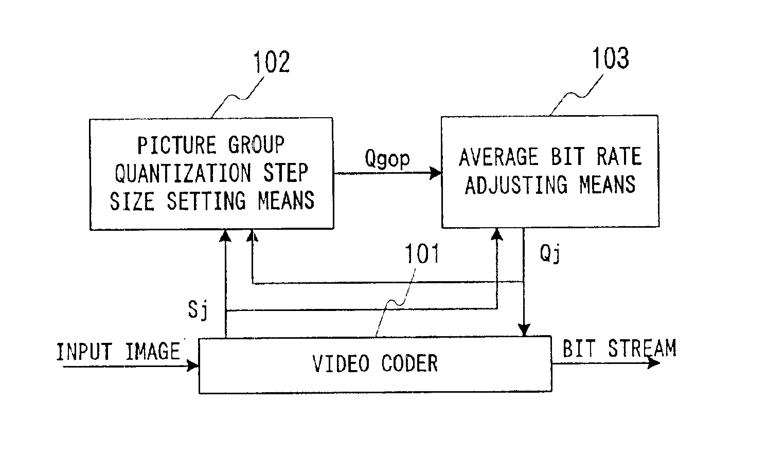
FIG. 1 is a view for describing a method of variable bit rate video coding according to the present invention. It is assumed that an MPEG-2 (ISO / ICE-13818) system is used as coding system. This coding system, however, is by no means limitative, and it is possible to use any coding technique so long as a scalar quantizing process is adopted and the bit rate is controlled according to the quantization step size. For example, it is possible to use an MPEG-1 (ISOIEC-11172) system, or an ITU-T H. 261 or ITU-T H. 263 system.

The quantization step size provided to the video coding means is used as a reference for bit rate control, and it by no means interferes with adaptive quantization corresponding to a local position in the picture. This means that the finally provided adaptive quantization step size may be different from the quantization step size provided as reference by the bit rate con...


PUM


Abstract

The quantization step size is set on the basis of features of image and the average bit rate is adjusted for the variable bit rate coding. In more specifically, the quantization step size is set such as to hold a constant coded image quality level over a plurality of groups of pictures. The quantization step size is adjusted from the excess or shortage of the actual generated bit count with respect to the average bit rate with reference to the quantization step size that has been set as above.

Description

BACKGROUND OF THE INVENTIONThe present invention relates to an apparatus for and a method of variable bit rate video coding and, more particularly, to those in which the generated code bit count is controlled in real time at a variable bit rate.MPEG-2 (ISO / IEC-13818-2), for instance, is well known in the art as a method of high efficiency video coding. In this method, the picture is divided into a plurality of blocks each constituted by a group of a plurality of pixels, and a special domain signal is converted to a frequency domain signal by executing discrete cosine transform (DCT) on each block. Each frequency component called DCT coefficient obtained by the discrete cosine transform, is quantized with a quantization step size, which is predetermined for each coefficient position (i.e., frequency). The quantized data is variable length coded by assigning variable length codes to the DCT coefficients. The coded data thus obtained is provided as a bit stream.FIG. 8 is a view for des...

Claims


Application Information

Patent Timeline
IPC IPC(8): H04N7/30H04N7/12H04N11/00H04N11/02H04N19/60H04N19/126H04N19/14H04N19/149H04N19/15H04N19/174H04N19/176H04N19/177H04N19/194H04N19/196H04N19/85
CPCH04N19/15H04N19/124H04N19/149H04N19/177H04N19/176H04N19/152
Inventor YOKOYAMA, YUTAKA
Owner NEC CORP
Why Eureka
Try Eureka