Method and apparatus for deriving motion information from projection data

a technology of motion information and projection data, applied in the field of medical imaging, can solve the problems of various motion-related image artifacts, blurring, streaking, discontinuities, etc., and achieve the effect of reducing or eliminating motion-related artifacts and facilitating data acquisition or image reconstruction

Inactive Publication Date: 2005-04-12
GENERAL ELECTRIC CO
View PDF4 Cites 37 Cited by
  • Summary
  • Abstract
  • Description
  • Claims
  • Application Information

AI Technical Summary

Benefits of technology

The present technique provides a novel method and apparatus for determining the motion of an internal tissue or organ undergoing dynamic movement. Particularly, the technique provides for a method and system for processing acquired projection data to determine the motion. The motion information may in turn be used to facilitate data acquisition or image reconstruction, such as by gating techniques, to reduce or eliminate motion related artifacts.

Problems solved by technology

CT imaging techniques, however, may present certain challenges when imaging dynamic internal tissues, such as the heart.
For example, in cardiac imaging, the motion of the heart causes inconsistencies in the projection data, which, after reconstruction, may result in various motion-related image artifacts such as blurring, streaking, or discontinuities.
In particular, artifacts may occur during cardiac imaging when projections that are not acquired at the same point in the heart cycle, i.e., the same phase, are used to reconstruct the image or images that comprise the volume rendering.
However, an ECG signal is a measure of the depolarization and repolarization of the cardiac muscle tissue, and does not actually represent the motion of the tissue.
Because of the indirect nature of this relationship, artifacts may still be present in the images reconstructed using gating techniques that rely upon ECG signals.

Method used


Image

  • Method and apparatus for deriving motion information from projection data
  • Method and apparatus for deriving motion information from projection data
  • Method and apparatus for deriving motion information from projection data

Examples


Embodiment Construction

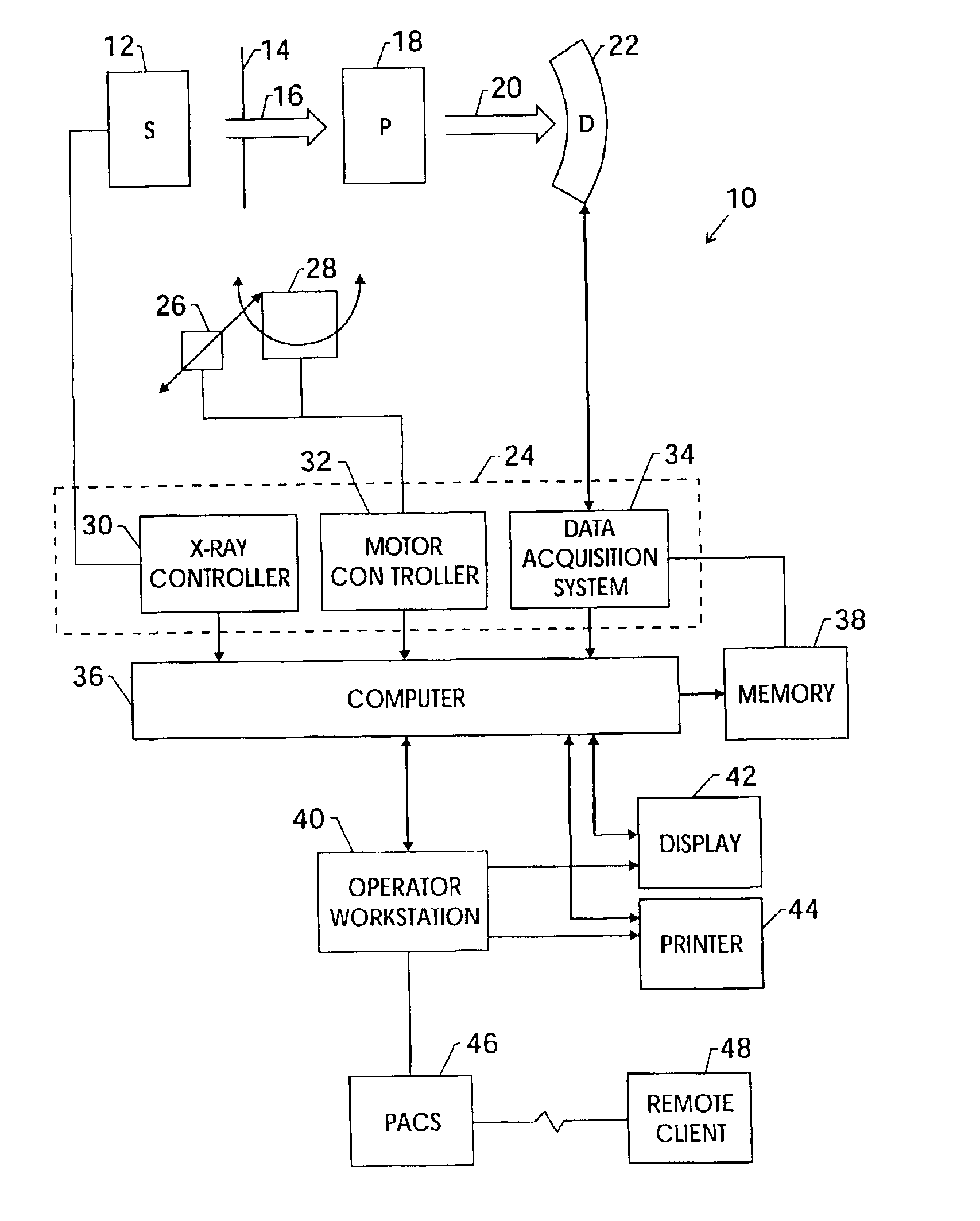
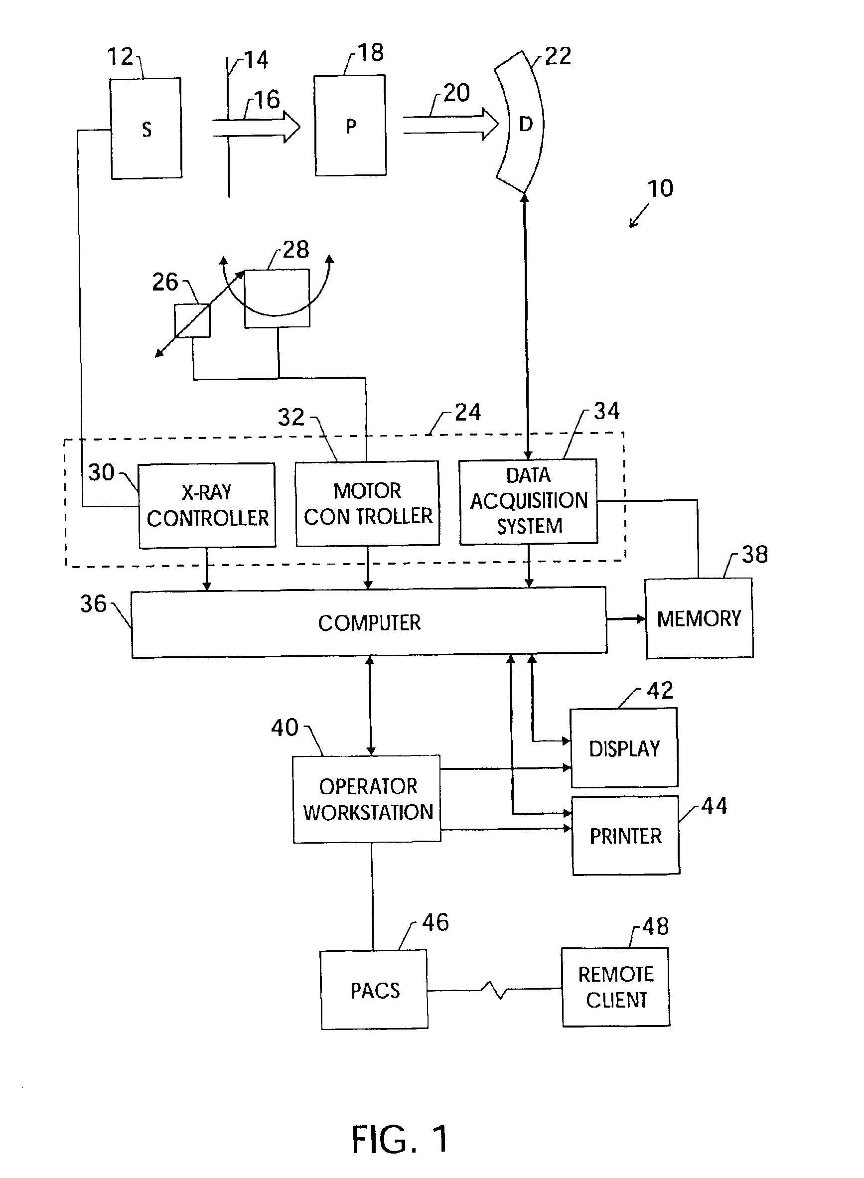
FIG. 1 illustrates diagrammatically an imaging system 10 for acquiring and processing image data. In the illustrated embodiment, system 10 is a computed tomography (CT) system designed to acquire X-ray projection data, to reconstruct the projection data into an image, and to process the image data for display and analysis in accordance with the present technique. In the embodiment illustrated in FIG. 1, imaging system 10 includes a source of X-ray radiation 12 positioned adjacent to a collimator 14. In this exemplary embodiment, the source of X-ray radiation source 12 is typically an X-ray tube.

Collimator 14 permits a stream of radiation 16 to pass into a region in which a subject, such as a human patient 18 is positioned. The stream of radiation 16 may be generally fan or cone shaped, depending on the configuration of the detector array, discussed below, as well as the desired method of data acquisition. A portion of the radiation 20 passes through or around the subject and impacts...


PUM

PropertyMeasurementUnit
included fan angleaaaaaaaaaa
CT detectoraaaaaaaaaa
volumeaaaaaaaaaa

Abstract

One or more techniques are provided for deriving motion data from a set of CT projection data. The techniques calculate moments associated with consistency conditions for the projection data to derive motion data from the projection data. One aspect of the present techniques uses the calculated moments to select projection data sets based upon the presence or absence of motion between the projection data sets. Periodicity information may then be extracted from the selected projection data sets. Another aspect of the present techniques uses projection data acquired by a slowly rotating volumetric CT gantry to allow the separation of a corruptive signal from a desired motion signal. Once separated, the desired motion signal may be used to identify projection data at a desired phase of motion.

Description

BACKGROUND OF THE INVENTIONThe present invention relates generally to the field of medical imaging and more specifically to the field of imaging dynamic, internal tissue, such as cardiac tissue, by computed tomography. In particular, the present invention relates to the generation of a signal representative of internal motion using projection data.Computed tomography (CT) imaging systems measure the attenuation of X-ray beams passed through a patient from numerous angles. Based upon these measurements, a computer is able to reconstruct images of the portions of a patient's body responsible for the radiation attenuation. As will be appreciated by those skilled in the art, these images are based upon separate examination of a series of angularly displaced projection images. A CT system processes X-ray projection data to generate 2D maps of the line integral of linear attenuation coefficients of the scanned object at multiple view angle positions. These data are then reconstructed to p...

Claims


Application Information

Patent Timeline
Patent Type & Authority Patents(United States)
IPC IPC(8): A61B6/03A61B6/00G01N23/04G01N23/02G06T11/00G06T5/00G06T5/50G06T7/20
CPCA61B6/032A61B6/503A61B6/541G01N23/046G06T11/005G06T7/2033G01N2223/612G06T2211/412Y10S378/901G01N2223/419G06T7/246
Inventor CESMELI, ERDOGANEDIC, PETER MICHAEL
Owner GENERAL ELECTRIC CO
Why Eureka
Try Eureka