
Miniature 2x2 magneto-optic switch

Inactive Publication Date: 2005-04-12
OPLINK COMM
View PDF16 Cites 5 Cited by
  • Summary
  • Abstract
  • Description
  • Claims
  • Application Information

AI Technical Summary

Benefits of technology

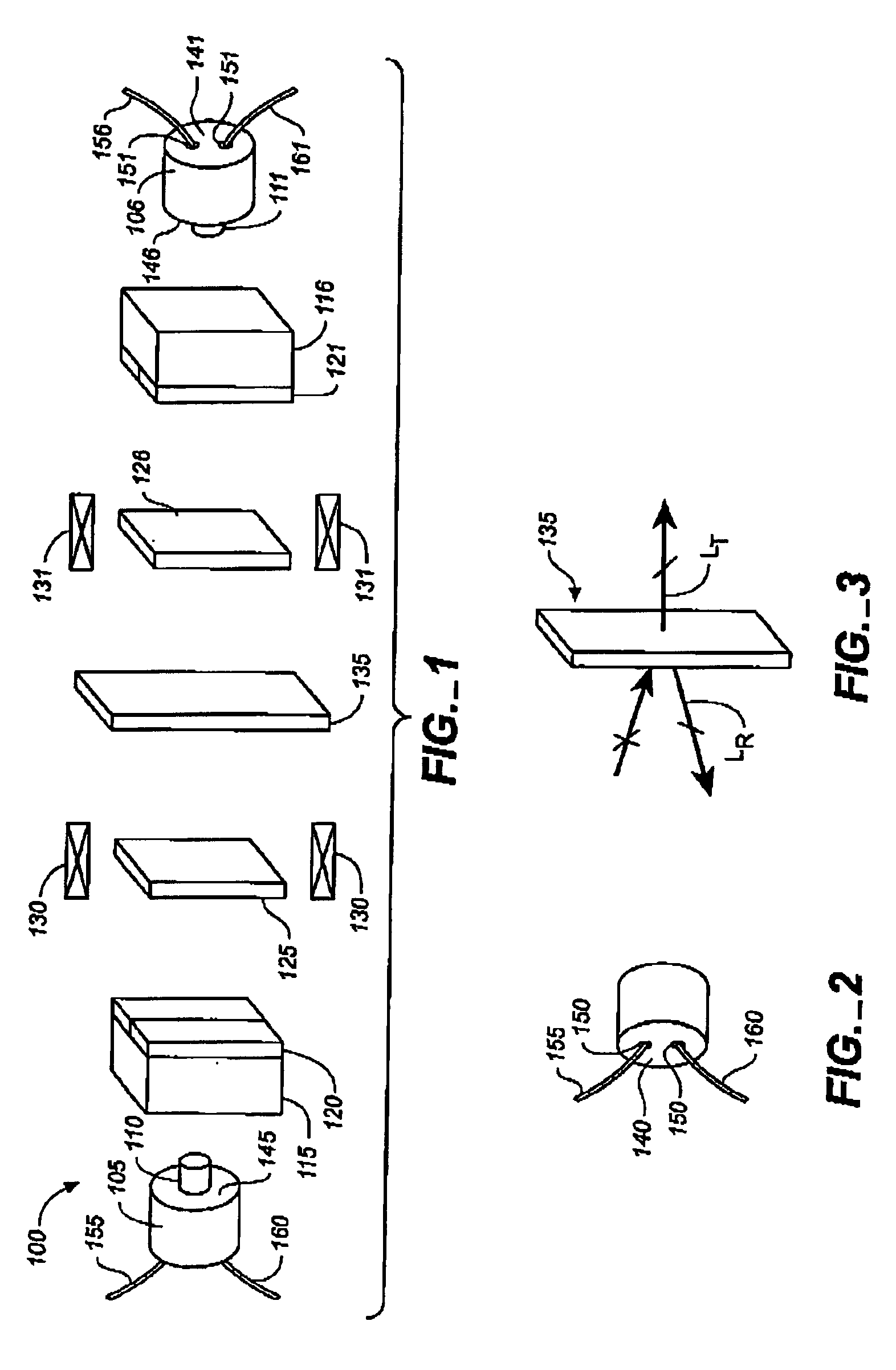
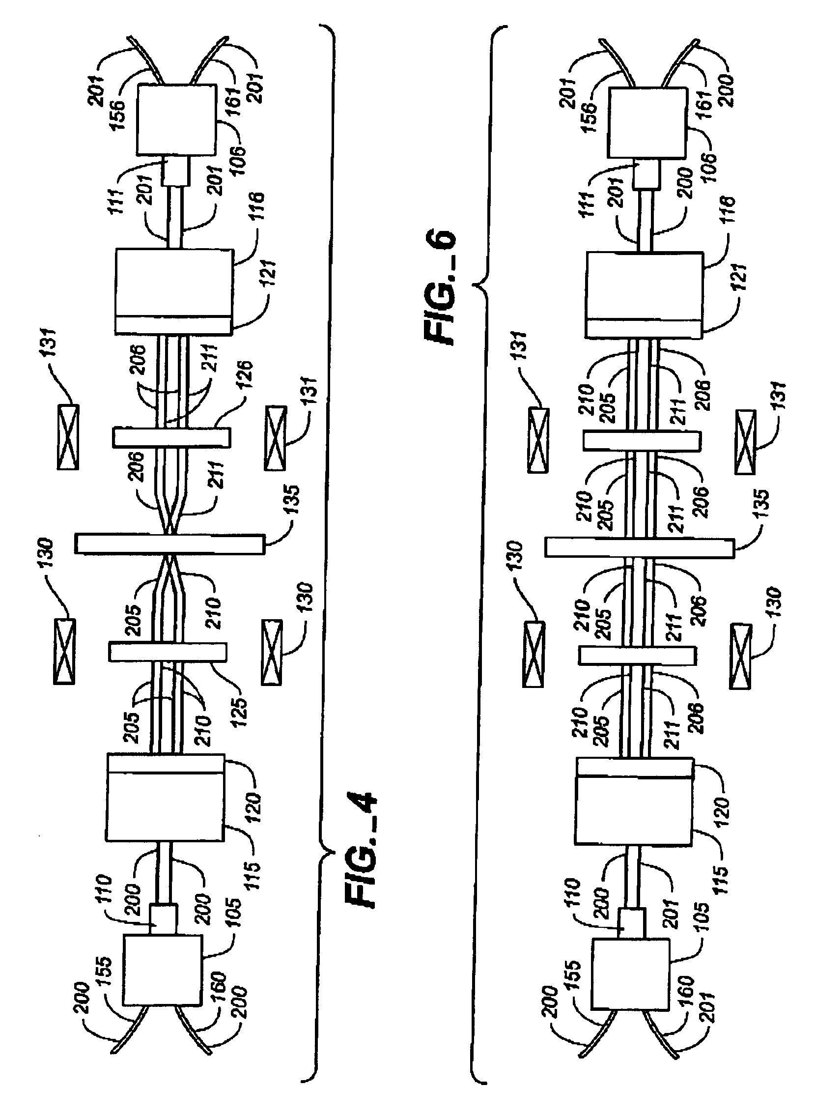
This invention can provide a reliable 2×2 optical switch by eliminating moving parts. The new invention allows one to build 2×2 optical switches with excellent optical performance, high switch speed, and compact size.

Problems solved by technology

However, the switching times of mechanical switches are limited to the millisecond range and the devices themselves are bulky.
Moreover, if motor-driven parts are used to operate the switch, the switch will have a limited operative lifetime and may suffer from reliability issues.

Method used


Image

  • Miniature 2x2 magneto-optic switch
  • Miniature 2x2 magneto-optic switch
  • Miniature 2x2 magneto-optic switch

Examples


Embodiment Construction

The present invention relates to an improvement in optical technology. The following description is presented to enable one of ordinary skill in the art to make and use the invention and is provided in the context of a patent application and its requirements. Various modifications to the invention will be readily apparent to those skilled in the art and the generic principles herein may be applied to other embodiments. Thus, the present invention is not intended to be limited to the embodiments shown, but is to be accorded the widest scope consistent with the principles and features described herein.

The present invention will be described in terms of particular optical switches having specific components having a specific configuration. Similarly, the present invention will be described in terms of particular optical switch components having specific relationships, such as distances or angles between components. However, one of ordinary skill in the art will readily recognize that t...


PUM


Abstract

A magneto-optical switch includes a first birefringent crystal configured to receive a light beam, a first half-wave compensator plate pair configured to receive split light beams from the birefringent crystal, a first Faraday rotator configured to receive the split light beams from the first half-wave compensator plate pair, and a beam splitter configured to receive the split light beam from the Faraday rotator. The first Faraday rotator is configured to change the polarization of a light beam passing through the first Faraday rotator.

Description

TECHNICAL FIELDThis invention relates generally to optical technology, and more particularly to magneto-optical switches.BACKGROUNDOptical switches are used in optical systems to switch a light beam between one or more input fibers and one or more output fibers. For example, optical switches are used in optical communication systems to connect and disconnect transmission paths to route light beams modulated with information, provide network protection, provide cross connection, and for add / drop applications. Optical switches also can be used to pulse a light source, e.g., a laser, or perform other functions with modulated or unmodulated light beams.One type of optical switch is a 1×2 optical switch, which provides optical switching between one input port and two output ports. It is known that 1×2 optical switches using refractive optics are very reliable, have small insertion loss, and are easy to manufacture. The 1×2 optical switch has been used widely in the telecommunications ind...

Claims


Application Information

Patent Timeline
IPC IPC(8): G02F1/09G02F1/01G02F1/31G02F1/29
CPCG02F1/31G02F1/09
Inventor LI, SHIFANGSHAO, QING
Owner OPLINK COMM
Learn More