Testing a communication network with a shared test port

a communication network and test port technology, applied in the field of telecommunications, can solve the problems of increasing the cost of testing a communication network, requiring separate test equipment, and testing consumes a number of test ports in the broadband dcs b, so as to reduce the cost, eliminate the cost of additional test equipment, and reduce the number of test ports

Inactive Publication Date: 2005-04-12
SPRINT CORPORATION
View PDF9 Cites 3 Cited by
  • Summary
  • Abstract
  • Description
  • Claims
  • Application Information

AI Technical Summary

Benefits of technology

The invention advantageously reduces the number of test ports in the cross-connect system. Also, the test system can also handle multiple independent test sessions with the plurality of the independent low data rate test signals, which eliminates the cost of additional test equipment. Thus, the reduced cost associated with the testing of the communication network reduces the overall costs of operating the communication network. Also, the plurality of the independent low data rate test signals through one shared test port allows a user to specify a mixture of test signals in one shared test port.

Problems solved by technology

One problem with this prior system is the testing consumes a number of test ports in the broadband DCS 120.
Also, another problem is separate test equipment is required for each test.
Unfortunately, these problems increase costs of testing a communication network.
Another problem is the test signal in this prior system does not provide a realistic mixture of test signals.
In one example, a technician may not be able to turn-up a DS3 and two STS-3cs because full multitasking is not available through one test port.

Method used


Image

  • Testing a communication network with a shared test port
  • Testing a communication network with a shared test port
  • Testing a communication network with a shared test port

Examples


Embodiment Construction

FIGS. 2-6B and the following description depict specific examples to teach those skilled in the art how to make and use the best mode of the invention. For the purpose of teaching inventive principles, some conventional aspects have been simplified or omitted. Those skilled in the art will appreciate variations from these examples that fall within the scope of the invention. Those skilled in the art will appreciate that the features described below can be combined in various ways to form multiple variations of the invention. As a result, the invention is not limited to the specific examples described below, but only by the claims and their equivalents.

Testing a Communication Network—FIGS. 2-3

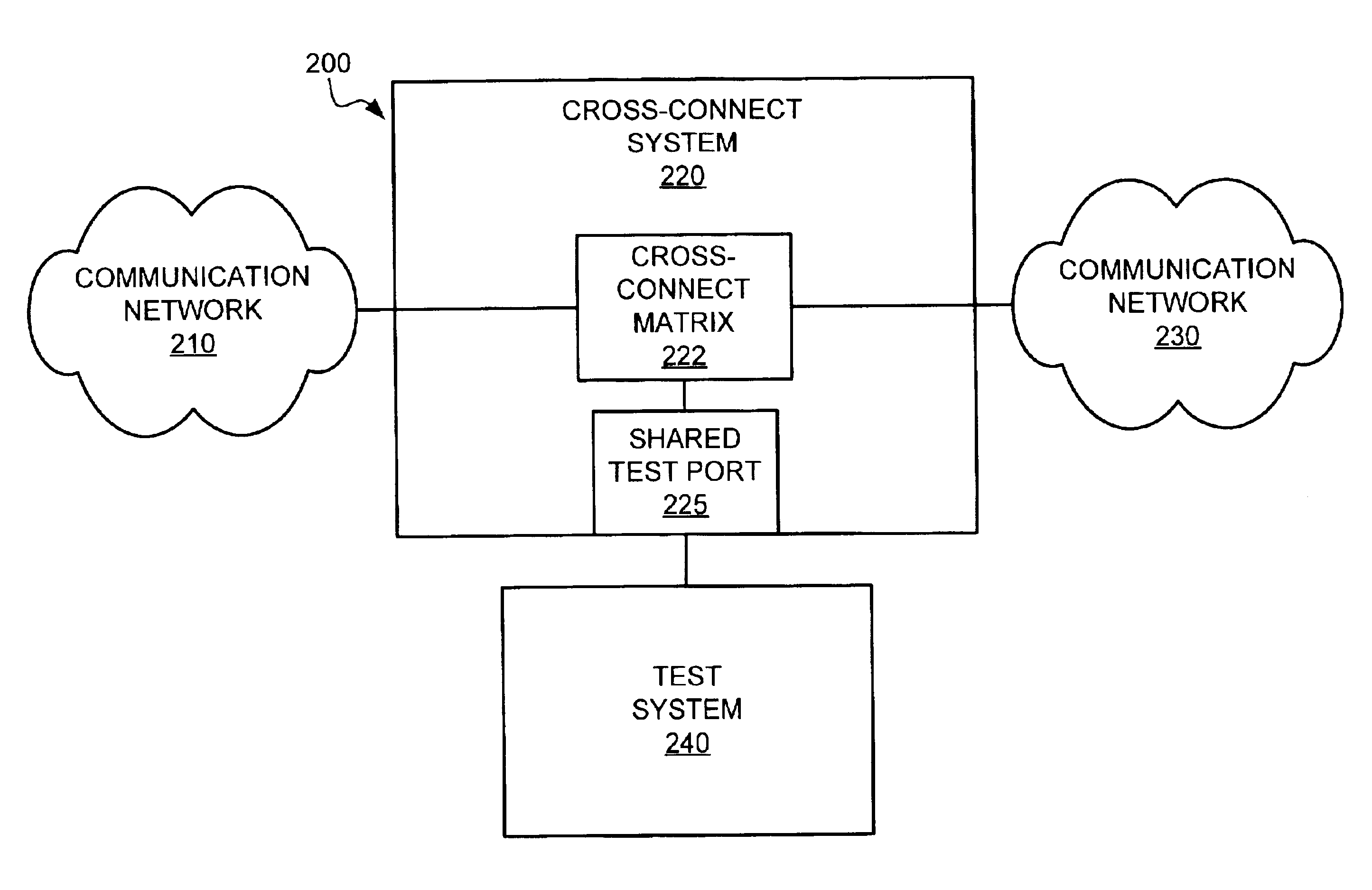
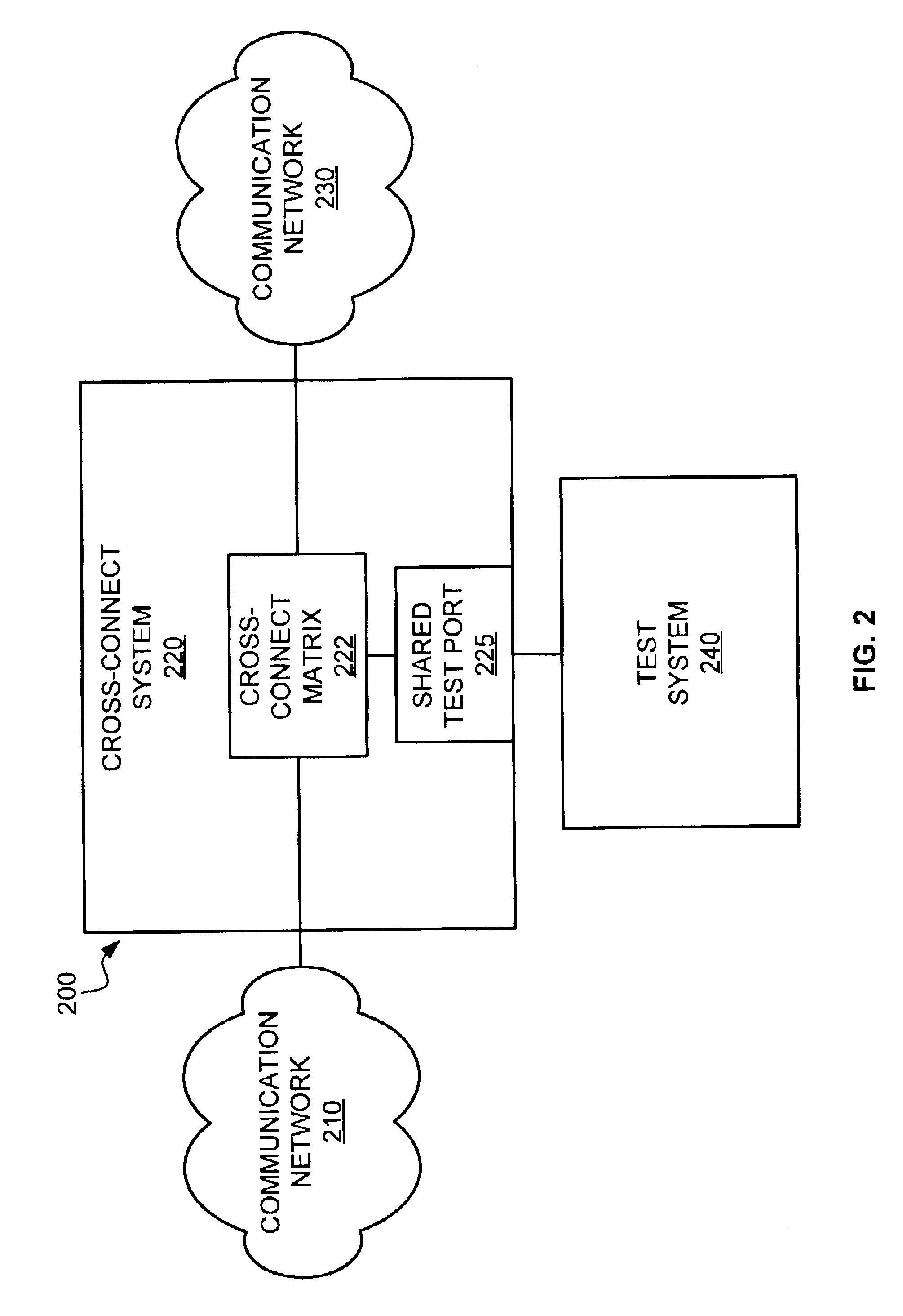
FIG. 2 depicts an illustration of a network 200 in an example of the invention. The network 200 includes a communication network 210, a cross-connect system 220, a communication network 230, and a test system 240. The cross-connect system 220 includes a cross-connect matrix 222 and a shared test...


PUM


Abstract

A system for testing a communication network includes a test system and a cross-connect system. The test system generates a plurality of independent low data rate test signals with first data rates. The test system combines the independent low data rate test signals to generate a high data rate test signal. The test system then transmits the high data rate test signal from the test system to a shared test port. The cross-connect system transfers the high data rate test signal to a cross-connect matrix that connects the independent low data rate test signals to the communication network. The cross-connect system then receives the independent low data rate test signals from the communication network into the shared test port. The cross-connect system transmits the high data rate test signal from the shared test port to the test system. The test system separates the high data rate test signal into the independent low data rate test signals. The test system then independently tests the independent low data rate test signals as separate test sessions.

Description

RELATED APPLICATIONSNot applicableFEDERALLY SPONSORED RESEARCH OR DEVELOPMENTNot applicableMICROFICHE APPENDIXNot applicableBACKGROUND OF THE INVENTION1. Field of the InventionThe invention is related to the field of telecommunications, and in particular, to systems and methods that test a communication network with a shared test port.2. Description of the Prior ArtTesting a communication network for monitoring, maintenance, and trouble shooting is an essential operation to ensure that the communication network is running optimally with minimal problems. In some examples, network operators use specialized test equipment to conduct bit error rate (BER) testing or analyze signals in the communication network. Minimizing the cost of these specialized test equipment reduces the overall costs of operating the communication network.FIG. 1 depicts an illustration of a communication network 100 in the prior art. FIG. 1 depicts a prior solution for testing the communication network 100 using...

Claims


Application Information

Patent Timeline
Patent Type & Authority Patents(United States)
IPC IPC(8): H04L12/26
CPCH04L43/50H04L12/2697
Inventor RICHARDS, DOUGLAS L.WOLFE, GREGORY A.HANSEN, KEVIN H.
Owner SPRINT CORPORATION
Why Eureka
Try Eureka