
System and method for monitoring remotely located objects

a technology for remotely located objects and systems, applied in the field of remote location object monitoring technology, can solve the problems of time-consuming and laborious investigations, site and operating state investigation by workers, and inability to accurately investigate the site and operating state in this manner

Inactive Publication Date: 2005-04-12
KOMATSU LTD +1
View PDF12 Cites 125 Cited by
  • Summary
  • Abstract
  • Description
  • Claims
  • Application Information

AI Technical Summary

Benefits of technology

Accordingly, it is an object of the present invention to make it possible to precisely monitor remotely located objects.

Problems solved by technology

However, efficient maintenance using this conventional method is difficult for the reasons provided below.
That is, investigations, by workers, of sites and the operating states of vehicles being rented is time-consuming and labor-intensive, and sites and operating states investigated in this manner are not necessarily accurate.
This leads to inefficiencies in that maintenance schedules of low efficiency are established, sites to be visited are overlooked, visits are made to sites which are close to other branch stores by servicemen from branch stores that are especially far away from these sites, the times at which the maintenance is carried out are too early or too late, and so forth.

Method used


Image

  • System and method for monitoring remotely located objects
  • System and method for monitoring remotely located objects
  • System and method for monitoring remotely located objects

Examples


Embodiment Construction

First, by reference to FIGS. 1 to 74, a description will be provided of the rental system as a whole to which the monitoring system of an embodiment of the present invention is applied. Thereafter, through reference to FIGS. 75 to 80, a description will be provided for those parts of this embodiment that are directly related to the present invention.

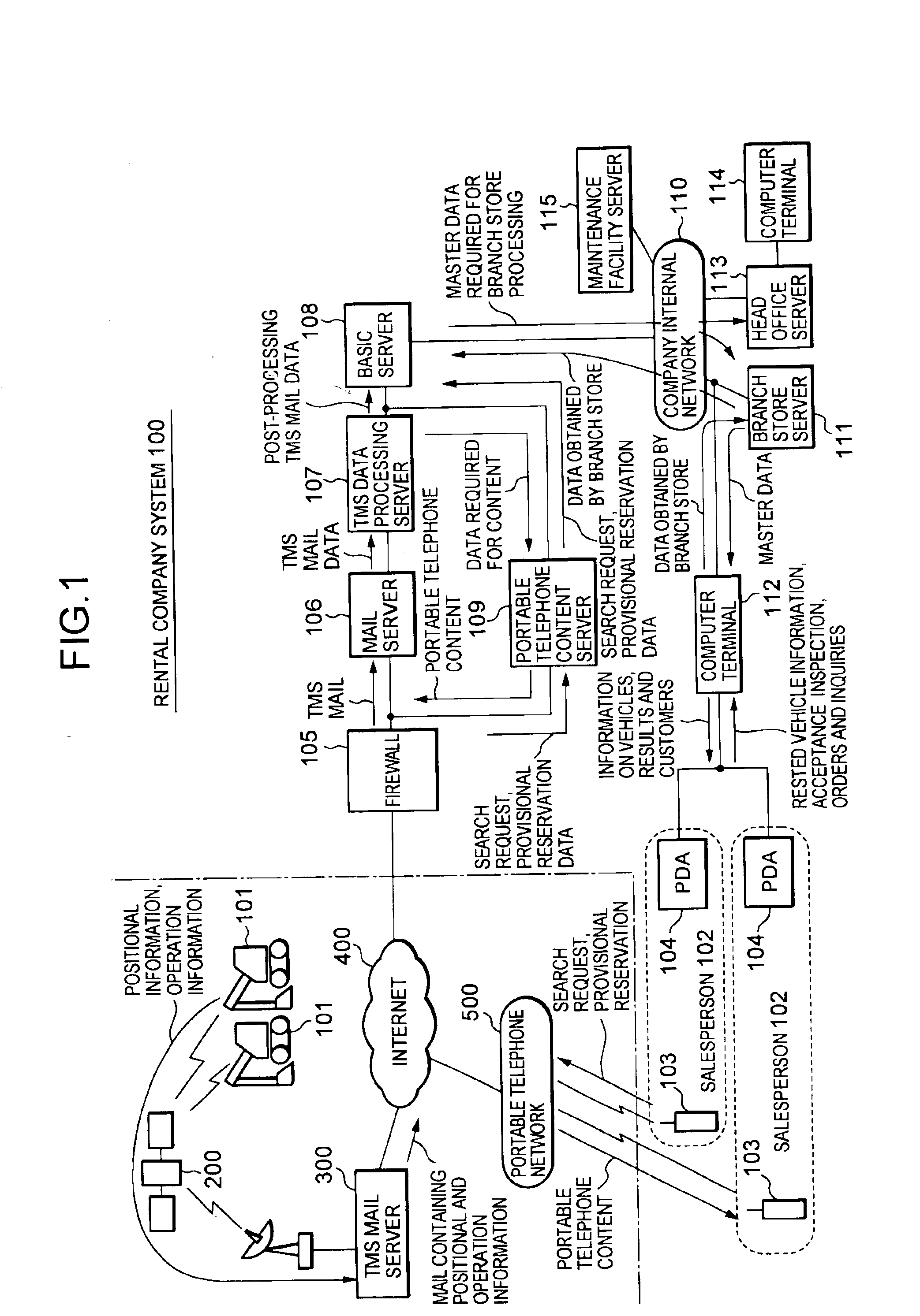
FIG. 1 shows the overall constitution of the rental system to which the monitoring system of an embodiment of the present invention is applied.

Such a system comprises: a computer system 100 for performing information processing, which is in the rental company (referred to hereinafter as “rental company system”); a multiplicity of construction vehicles 101, 101, . . . which are rental goods, and a TMS (Tele-management System) mail server 300 that remotely captures the respective positions of these construction vehicles 101, 101, . . . , operating states thereof, and the like.

The construction vehicles 101, 101, . . . and the TMS mail serve...


PUM


Abstract

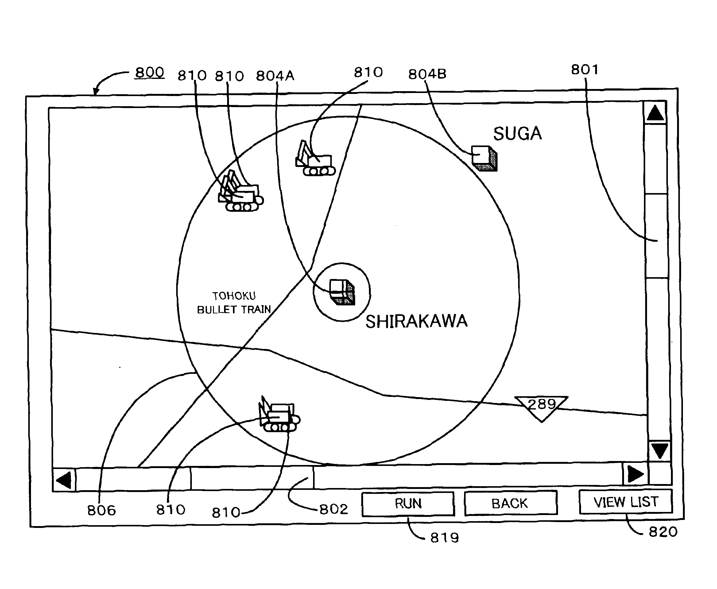
The present invention makes it possible to precisely monitor remotely located objects. The construction vehicles each contain a GPS apparatus, and various sensors for capturing the states of vehicle parts, and are capable of reporting, as required, the current position captured by the GPS apparatus, and operation information captured by the various sensors to the TMS mail server via the satellite communication system. The TMS mail server and the rental company system are capable of communicating at any time via a communication network between computers. The TMS mail server collects the latest positional information, operation information, and so forth, on the construction vehicles being rented and relays such information in the form of electronic mail, for example, to the rental company system as required or periodically. The rental company system displays construction vehicles by means of marks in the current positions of the construction vehicles on a map represented by map data, or in the form of a list, based on the collected positional information and operation information, on a branch store computer terminal. The system also displays the operating states of rented construction vehicles based on the collected operation information, on the branch store computer terminal.

Description

BACKGROUND OF THE INVENTION1. Field of the InventionThe present invention relates to a technology for monitoring remotely located objects, and relates, for example, in a rentals business that provides machine and vehicle rentals, to a technology which is adapted as a support apparatus or similar for establishing a maintenance scheme for the machines and vehicles being rented.2. Description of the Related ArtThe description that follows is based on the example of a construction vehicle rental company.Such a company normally employs a business model in which a plurality of branch stores are situated in different locations and a plurality of construction vehicles are owned and utilized individually by each branch store. Consequently, the maintenance of the construction vehicles is carried out by each branch store, and each branch store performs maintenance on construction vehicles in its possession by means of the following method, for example.In other words, as occasion calls, the cle...

Claims


Application Information

Patent Timeline
IPC IPC(8): G08G1/123G06Q30/06G06Q50/10G06Q50/00
CPCG08G1/20
Inventor SHIKE, CHIKASHIABE, NORIAKI
Owner KOMATSU LTD
Learn More