Disc driving apparatus

Inactive Publication Date: 2005-04-12
PIONEER CORP
View PDF6 Cites 13 Cited by
  • Summary
  • Abstract
  • Description
  • Claims
  • Application Information

AI Technical Summary

Benefits of technology

[0019]According to the disc driving apparatus of the third aspect of the present invention, the cam follower is permitted to move away from the first guide surface of the guide groove to cause a structural element, for example, the turntable t

Problems solved by technology

As a result, heavy load is applied to a motor for driving the disc to cause problems, when moving the clamping member and the turntable away from each other.
Use

Method used


Image

  • Disc driving apparatus
  • Disc driving apparatus
  • Disc driving apparatus

Examples


Embodiment Construction

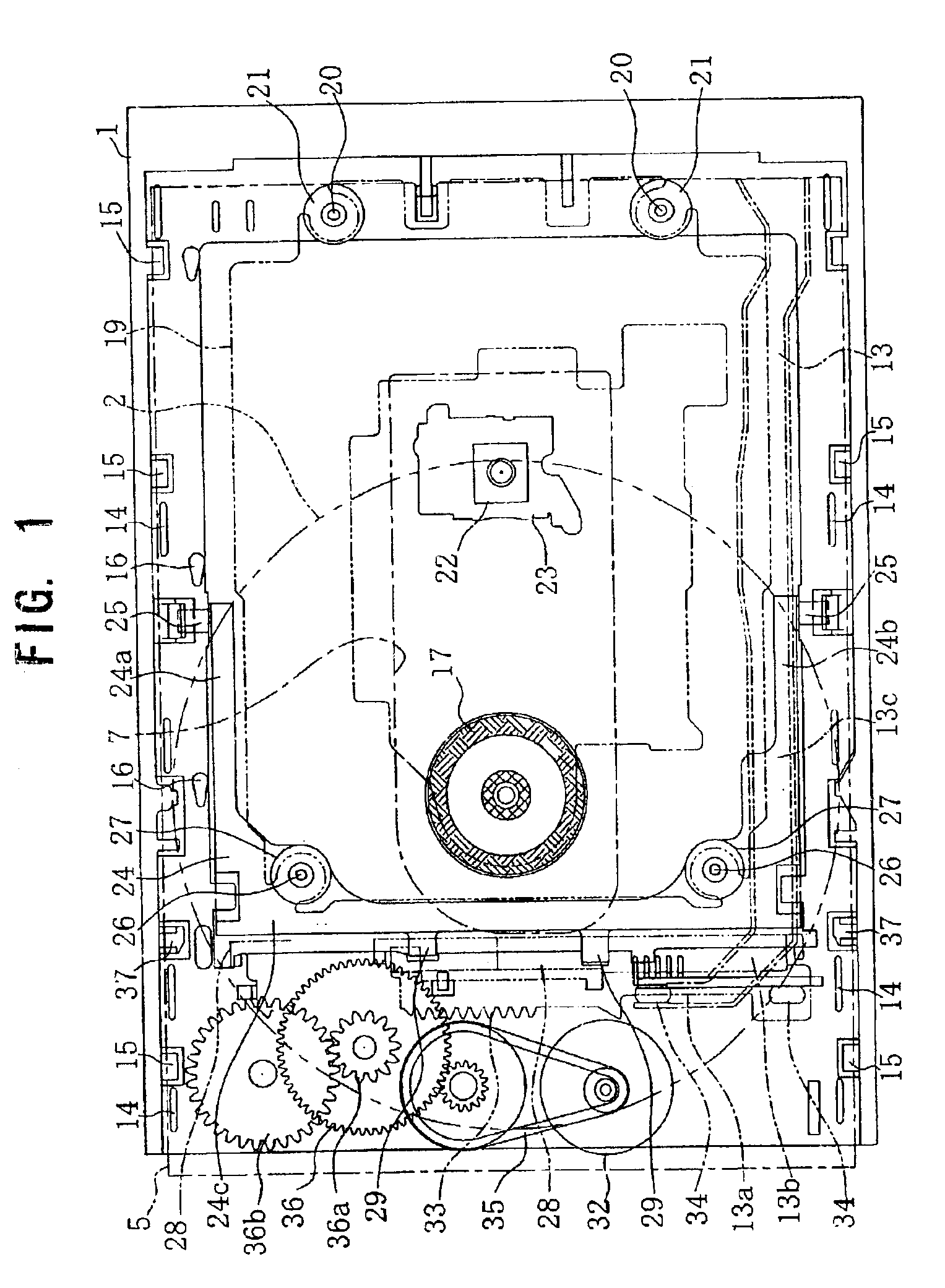
[0033]Now, an embodiment of a disc driving apparatus of the present invention will be described in detail below with reference to the accompanying drawings.

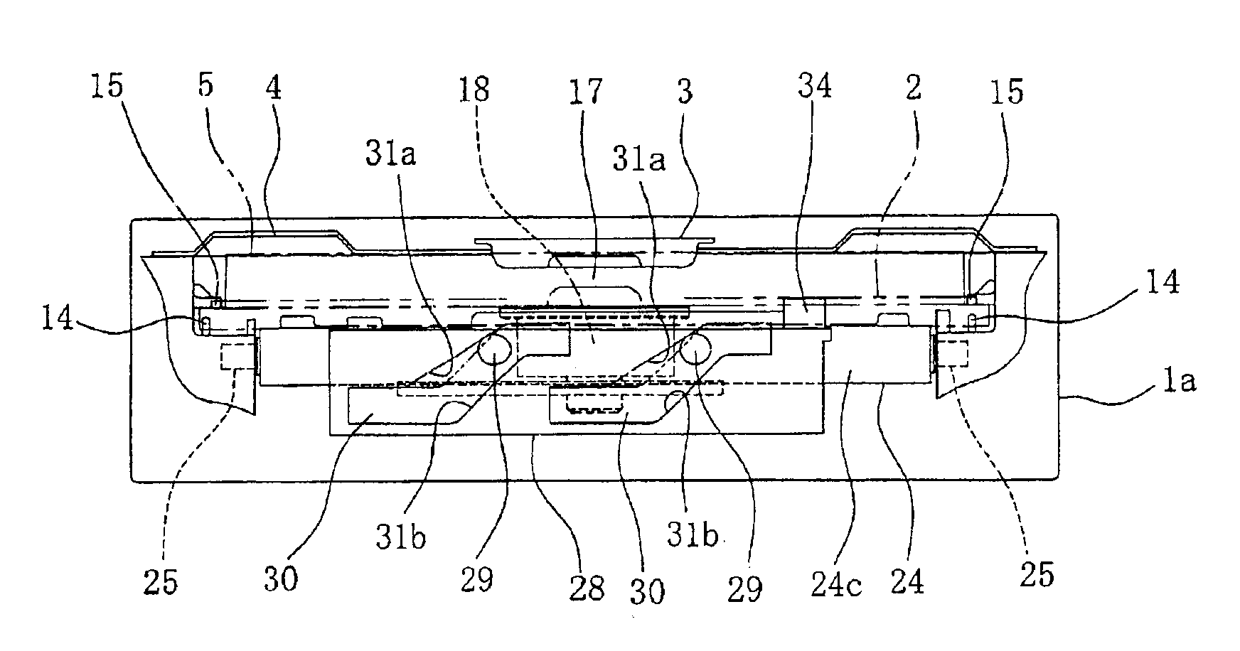
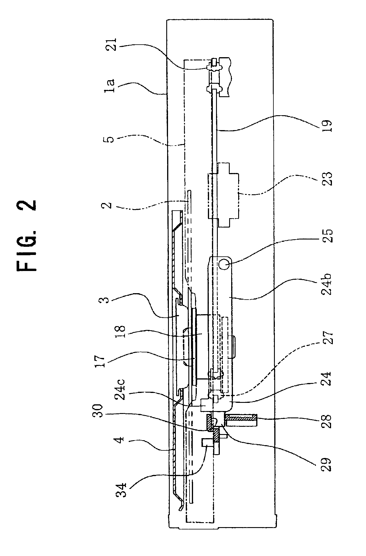
[0034]As shown in FIGS. 1 to 6, the disc driving apparatus has a casing 1 covered with a cover 1a. The casing 1 has a flat rectangular parallelepiped shape extending in the horizontal direction in the embodiment. The disc driving apparatus may be used in a turned state by 90 degrees so as to extend vertically. In such a case, a clamping member, a turntable and the other structural components are disposed vertically.

[0035]A top plate 4, which has a supporting hole for supporting the clamping member 3 for a disc 2, is horizontally secured on the upper portion of the casing 1. The clamping member 3 is supported horizontally in the casing 1 so as to be fitted in the supporting hole of the top plate 4. The clamping member 3 is formed of material, which a magnet attracts. Alternatively, the clamping member 3 may be provided a magnetica...


PUM


Abstract

A disc driving apparatus comprises a turntable, a clamping member and a cam mechanism. A disc is to be placed on the turntable. The clamping member holds the disc between the turntable and the clamping member with a magnetic attracting force. The cam mechanism causes a relative movement between the turntable and the clamping member to move any one of them away from another thereof or move them closer to each other. The cam mechanism has a cam and a cam follower. The cam has a contour by which a variation rate of displacement of the cam follower relative to a moving amount of the cam when the turntable and the clamping member move away form each other becomes smaller than a variation rate thereof when the turntable and the clamping member move close to each other.

Description

BACKGROUND OF THE INVENTION[0002]1. Field of the Invention[0003]The present invention relates to a disc driving apparatus for driving a disc such as a CD and DVD.[0004]2. Description of the Related Art[0005]A disc driving apparatus includes a turntable on which a disc is to be placed and a clamping member for holding the disc between the turntable and the clamping member with a magnetic attracting force. In addition, there is provided a cam mechanism, which has a cam and a cam follower, for causing a relative movement between the turntable and the clamping member to move any one of them away from another thereof or move them closer to each other. More specifically, when the disc is to be loaded on the turntable, the cam is operated to turn in a direction to move the turntable and the clamping member away from each other through the cam follower. Then, an empty disc tray is moved away from between the turntable and the clamping member. After the disc is placed on the empty disc tray,...

Claims


Application Information

Patent Timeline
IPC IPC(8): G11B17/028G11B17/04
CPCG11B17/056G11B17/0284G11B17/0288
Inventor KONNO, YOUICHIISHII, KATSUMI
Owner PIONEER CORP
Why Eureka
Try Eureka