Lead-in structure and a fixing flange for a turbo generator

Inactive Publication Date: 2005-04-19
TRIOGEN
View PDF10 Cites 2 Cited by
  • Summary
  • Abstract
  • Description
  • Claims
  • Application Information

AI Technical Summary

Benefits of technology

[0008]A considerable advantage of the invention is the hermetic connection to the rest of the process, in a manner which is as leak-proof as possible, without using difficult welded joints or expensive special sealing structures. Another advantage is that the leaks which, notwithstanding, occur due to e.g. roughness and thermal movement in the sealing surfaces, will now be guided to the channelling of the expanded circulating medium and further to the condenser, which is hardly harmful in practice. It is thus possible to avoid a harmful leak outside the system.
[0009]It is still possible to fix the pipes to the fixing flange by welding, which prevents pipe leaks. A particular advantage is that, for maintenance work, the turbo generator can now be fixed to this fixing flange in a fast, easy and detachable manner, for example by a bolted joint. Thus, the fixing flange may remain in its place and its welded joints do not need to be opened. The fixing flange and the parts connected to it are simultaneously exposed for on-site maintenance. The closing valve of the fixing flange is placed in a tubular channel where it is exposed for maintenance and from which it can be released and taken out for example to be exchanged.

Problems solved by technology

A problem in the end flange is particularly the tightness of the flange joint.
D:194, 1991, Ministry of Trade and Industry, Department of Energy, Helsinki, it has also been found in practice that particularly the inlet of the vaporized circulating medium tends to leak, which is due to the thermal movement which is a problem known as such in power plant technology.
It is also known that the flange joint or other lead-in ducts and leakages are sealed with a welded joint, but it is then obvious that this makes the releasing, re-mounting and maintenance of the turbo generator considerably more difficult.

Method used


Image

  • Lead-in structure and a fixing flange for a turbo generator
  • Lead-in structure and a fixing flange for a turbo generator
  • Lead-in structure and a fixing flange for a turbo generator

Examples


Embodiment Construction

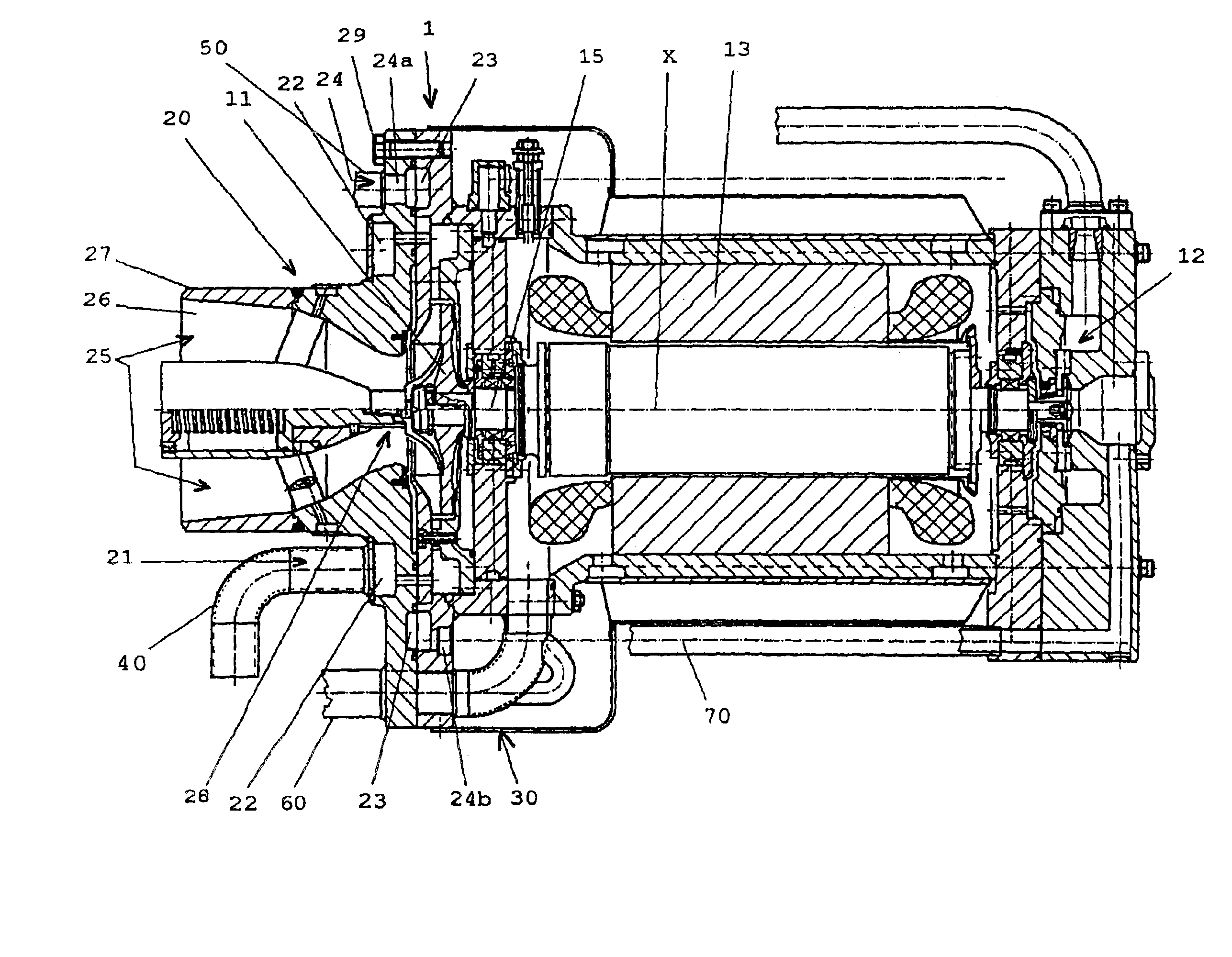
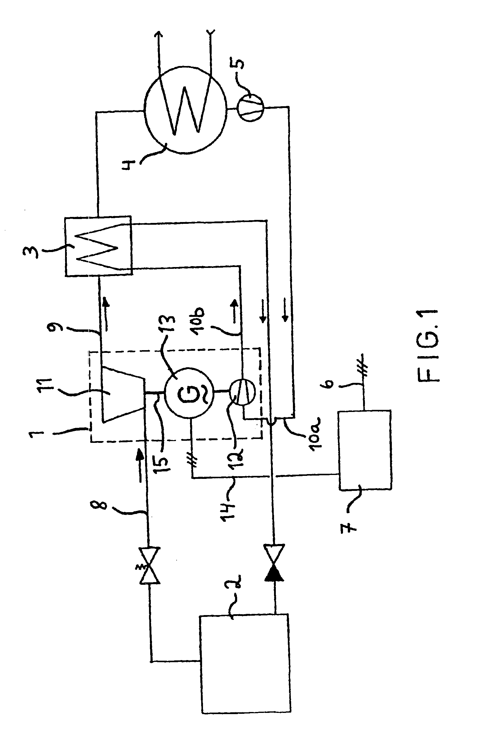
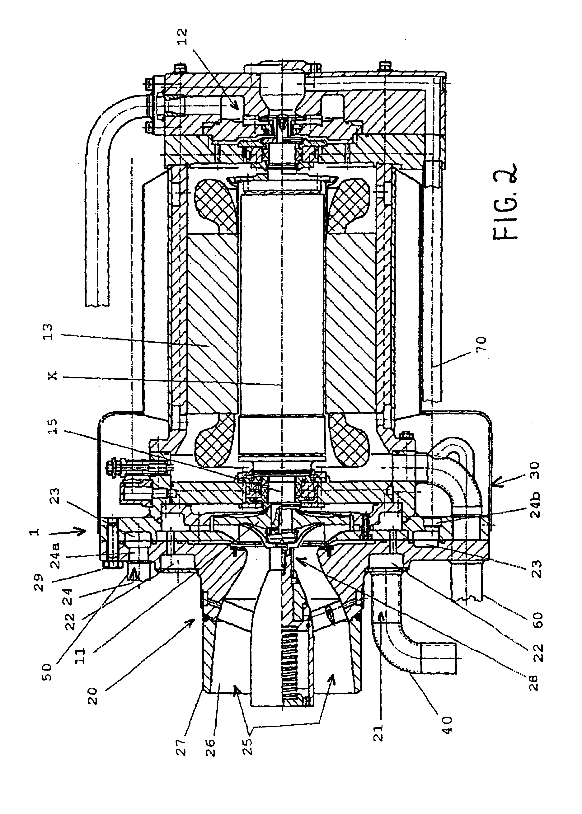
[0014]With reference to FIG. 1, the used circulating medium is vaporized by means of e.g. waste thermal energy in a boiler 2, is expanded in a turbine 11 of a turbo generator 1, is cooled in a possible recuperator 3 in case this is installed in the system, and is condensed in a condenser 4, in which the condensing agent is for example raw water or air. The feed pump 12 of the turbo generator 1 feeds the circulating medium directly or through the recuperator 3 back to the boiler 2. Normally, the system also comprises a pre-feed pump 5. The high-frequency current 14 produced by the generator 13 included in the turbo generator 1 is processed in a desired manner, e.g. to a standard current 6 suitable for a normal electric power network by means of an electric circuit 7 known as such. The generator 13 used can be a so-called asynchronous or synchronous machine, wherein the magnetization or the magnetization current for the rotor or stator of the generator 13, obtained from e.g. the circu...


PUM


Abstract

The invention relates to a lead-in structure for coupling of a turbo generator in a circulating process of a circulating medium. The turbo generator includes a turbine and a generator as well as possibly also a feed pump enclosed in a common casing structure. The casing structure also includes at least a first duct for hot, steam-like circulating medium entering the turbine, a second duct for circulating medium exiting the turbine, and a third duct for cooled liquid circulating medium, which, for example, enters the feed pump. The third duct includes an annular channel that is placed, preferably concentrically, around the second duct, which includes an annular channel. The first duct includes an annular channel that is placed, preferably concentrically, between the second duct and the annular channel of the third duct. The fixing flange applying the lead-in structure may include a closing valve that is controlled with a pressurized medium and that is arranged to keep the tubular channel of the second duct normally open and to keep it closed for releasing the casing element, wherein the closing valve is placed inside the tubular channel.

Description

TECHNICAL FIELD OF THE INVENTION[0001]The invention relates to a lead-in structure for coupling a turbo generator in a circulation process of a circulating medium. The invention also relates to a fixing flange for coupling a turbo generator in the circulation process of a circulating manner in a detachable manner for maintenance.DESCRIPTION OF BACKGROUND ART[0002]Hermetic high-speed turbo generators are known, in which the hermetic property is based on the fact that the turbine, the generator and preferably also the feed pump are arranged on the same shaft and within a common casing, wherein external leaks e.g. from rotary shaft seals are avoided and only internal leaks between said different components are possible; in other words, the turbo generator is externally hermetic. One known turbo generator is disclosed in patent publication FI 66234, whereby the device is used to convert thermal energy into electric energy. The circulating medium used in the process is vaporized in a the...

Claims


Application Information

Patent Timeline
IPC IPC(8): F01D25/24F01D15/00F01D9/00F01D5/02F01D15/10F01D5/04F01D25/26F01D9/06F01D25/00F01D25/30
CPCF01D5/043F01D9/06F01D25/265F01D25/24F01D15/10
Inventor LARJOLA, JAAKKO
Owner TRIOGEN
Why Eureka
Try Eureka