
Ball valve assembly

Active Publication Date: 2016-10-18
KELSO TECH
View PDF18 Cites 4 Cited by
  • Summary
  • Abstract
  • Description
  • Claims
  • Application Information

AI Technical Summary

Benefits of technology

The current invention is an improved bottom outlet ball valve assembly designed to prevent leakage of liquid from a mobile tank or large tank-like container within a rail car tank or other large tank-like container. The valve assembly includes a ceramic wiper and ball component that resist scoring, abrasion, and chemical exposure corrosion. The assembly housing is made of metal, and the ball component is made entirely of ceramic material, preferably zirconium oxide. The technical effects of the invention include reducing leakage, preventing damage and corrosion, and improving efficiency in the transportation of liquid commodities.

Problems solved by technology

The seat retainer applies mechanical pressure to the bottom seat against the ball component, thereby creating a leak tight seal.

Method used


Image

  • Ball valve assembly
  • Ball valve assembly
  • Ball valve assembly

Examples


Embodiment Construction

The Preferred Embodiment of Improved Ball Valve Assembly 100

[0087]A. Valve body 1

[0088]1. Body Tube 1c

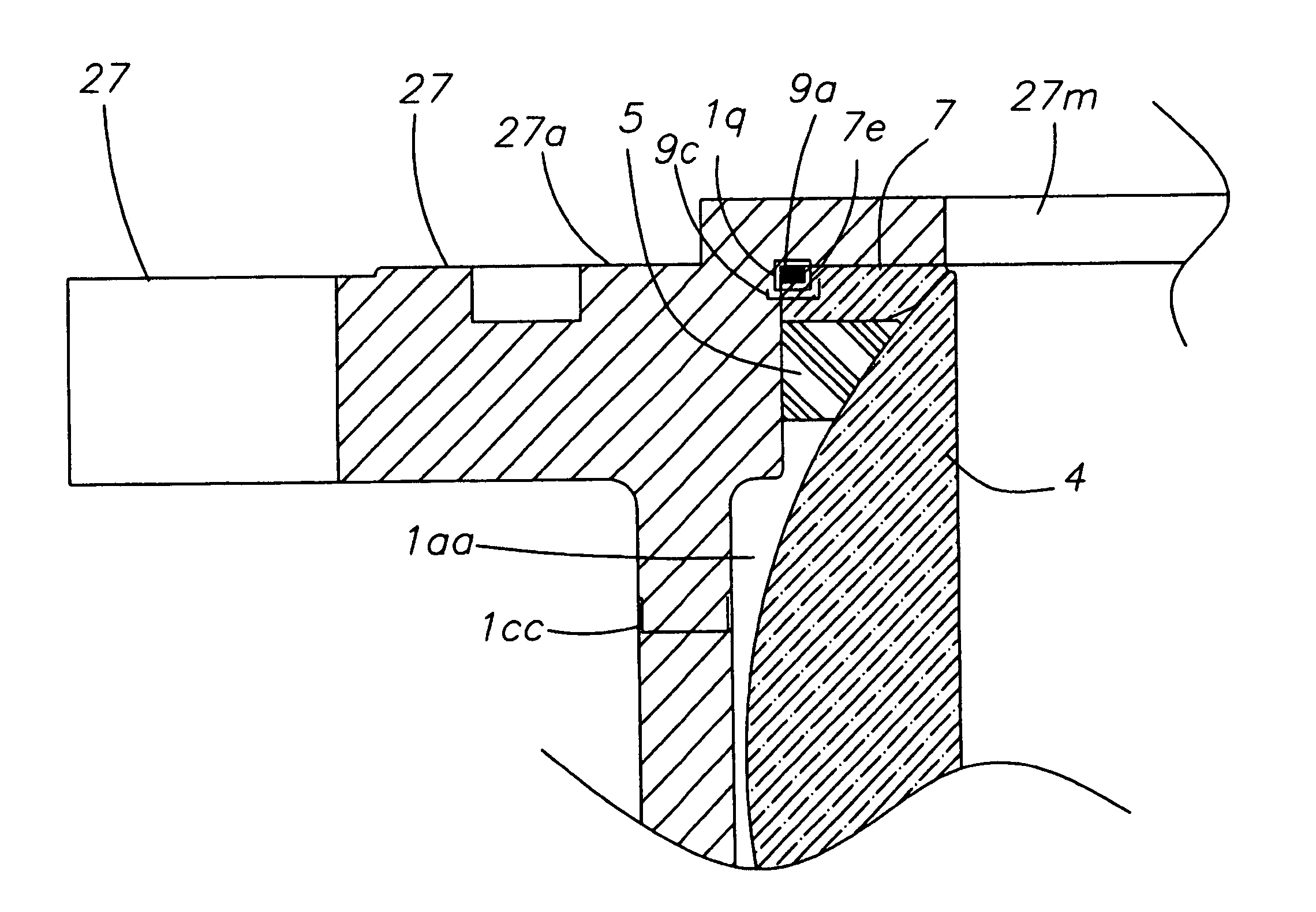
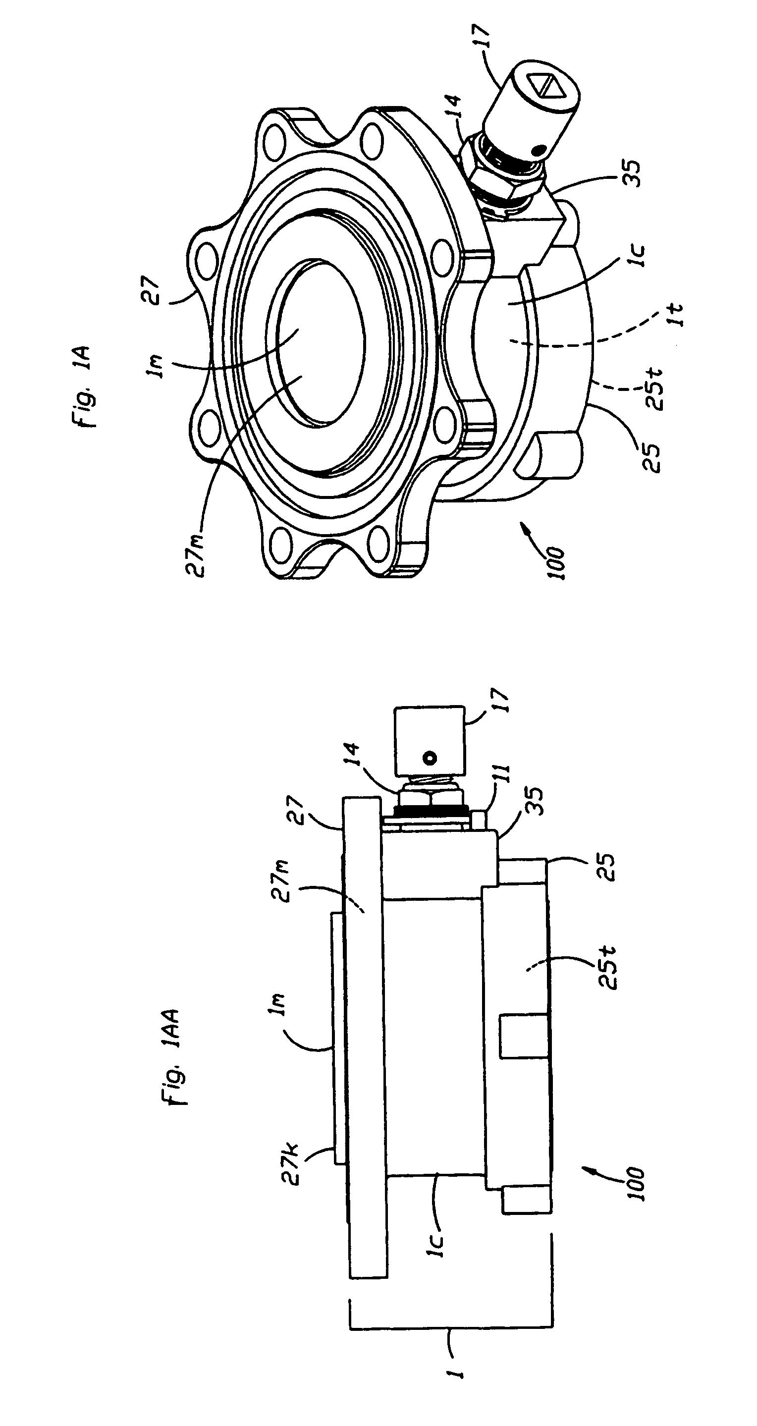
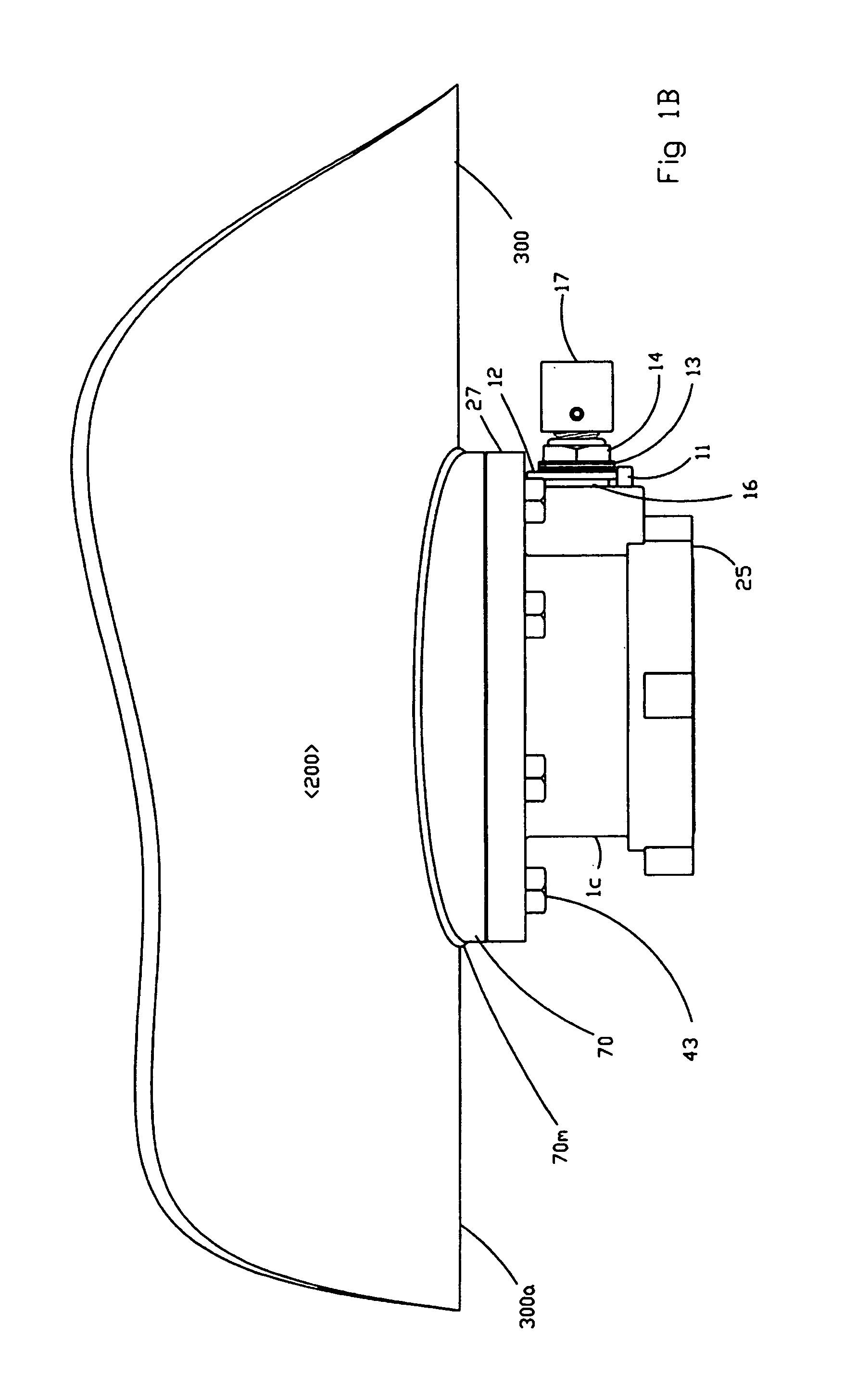
[0089]Referring initially to FIGS. 1A, 1AA, 1B and 1BB, in the preferred embodiment the improved tank bottom outlet ball valve assembly 100 [hereinafter ball valve assembly 100] comprises a single sole and only valve body 1. Valve body 1 is preferably made of steel and attaches to bottom surface 300a of rail car tank 300 or other tank-like container. Valve body 1 can be cast as a single object or otherwise fabricated and assembled; welding 41 is one example in the preferred embodiment. welding as one example. Valve body 1 is preferably approximately (i) 12.25 inches in total maximum longitudinal length 1 and (ii) 54.41 inches in maximum diameter. Valve body 1 comprises a single top flange 27, single bottom flange 25, and single body tube 1c.

[0090]Referring to FIGS. 1A, 1AA, 1B, 1BB, 10A, 10B and 10C, 16A and 16B, body tube 1c comprises a (i) body tube interior surface 1f and an ex...


PUM


Abstract

Described herein is an improved ball valve assembly for use in a tank or a tank-like container. This improved ball valve assembly prevents leakage of a liquid with corrosive and abrasive contaminants within the tank or a tank like container. This improved ball valve assembly is especially useful in a railroad tank car that contains a liquid commodity in whenever a tank is mobile and subjected to wide temperature variations. The improved ball valve assembly contains a ball component made of a ceramic material. A ceramic wiper (i) mechanically seals against the ball component and (ii) prevents contaminants from embedding within, or otherwise abrading, top and bottom seats within the ball valve assembly. Also contained in the preferred embodiment of this invention is an improved drive coupling that (i) eliminates the previously existing need for custom square drive tool (ii) pre-attached to the ball valve assembly. The current invention also includes an improved stem packing assembly that reduces the number of annular components along the stem of the ball valve assembly.

Description

BACKGROUND OF THE INVENTION[0001]The current invention is directed to ball valve assemblies that are configured to prevent leakage of liquids from within mobile tanks or other large tank-like containers. More particularly, but not exclusively, the current invention is directed to a ball valve assembly configured to prevent leakage of liquid commodities from railroad tank cars. Railroad tank cars that ship liquid commodities are generally divided into two categories: low pressure (general purpose) and (ii) high pressure tank cars. The present invention addresses general purpose tanks as (i) railroad cars that transfer these commodities from the tank cars (ii) through a valve located at the bottom center position of the tank [‘bottom outlet valve’]. These prior existing valves contain a variety of structures such as, but not exclusively, plug, butterfly or ball valves. The most common prototype is the ball valve, and most particularly this invention pertains to the ball valve variety....

Claims


Application Information

Patent Timeline
IPC IPC(8): F16K5/06
CPCF16K5/0694F16K5/0657
Inventor LACROIX, BARRY
Owner KELSO TECH
Learn More