Reed valve assembly

a valve assembly and reed technology, applied in the field of engine parts, can solve the problems of increasing assembly cost, affecting the operation of the valve, wear and tear etc., and achieve the effect of maximizing the durability of the reed petals and maximizing the desirable airflow

Inactive Publication Date: 2005-04-19
MOTO TASSINARI
View PDF23 Cites 18 Cited by
  • Summary
  • Abstract
  • Description
  • Claims
  • Application Information

AI Technical Summary

Benefits of technology

[0010]It is a further object of the present invention to maximize the durability of the reed petals.
[0011]It is a further object of the present invention to maximize the desirable airflow through the reed valve.

Problems solved by technology

One problem with the traditional 2-stroke motor reed valve is wear and tear on the reed petals 14.
The screws 30 required are special order screws increasing the cost of assembly.
The stripped condition of the screws 30 can result in the screws 30 falling out of the reed valve 20 and into the motor, significantly damaging the motor.
Another problem with the reed valve 20 design is assembly time.
Labor costs cause the reed valve 20 to be unduly expensive.

Method used


Image

  • Reed valve assembly
  • Reed valve assembly
  • Reed valve assembly

Examples


Embodiment Construction

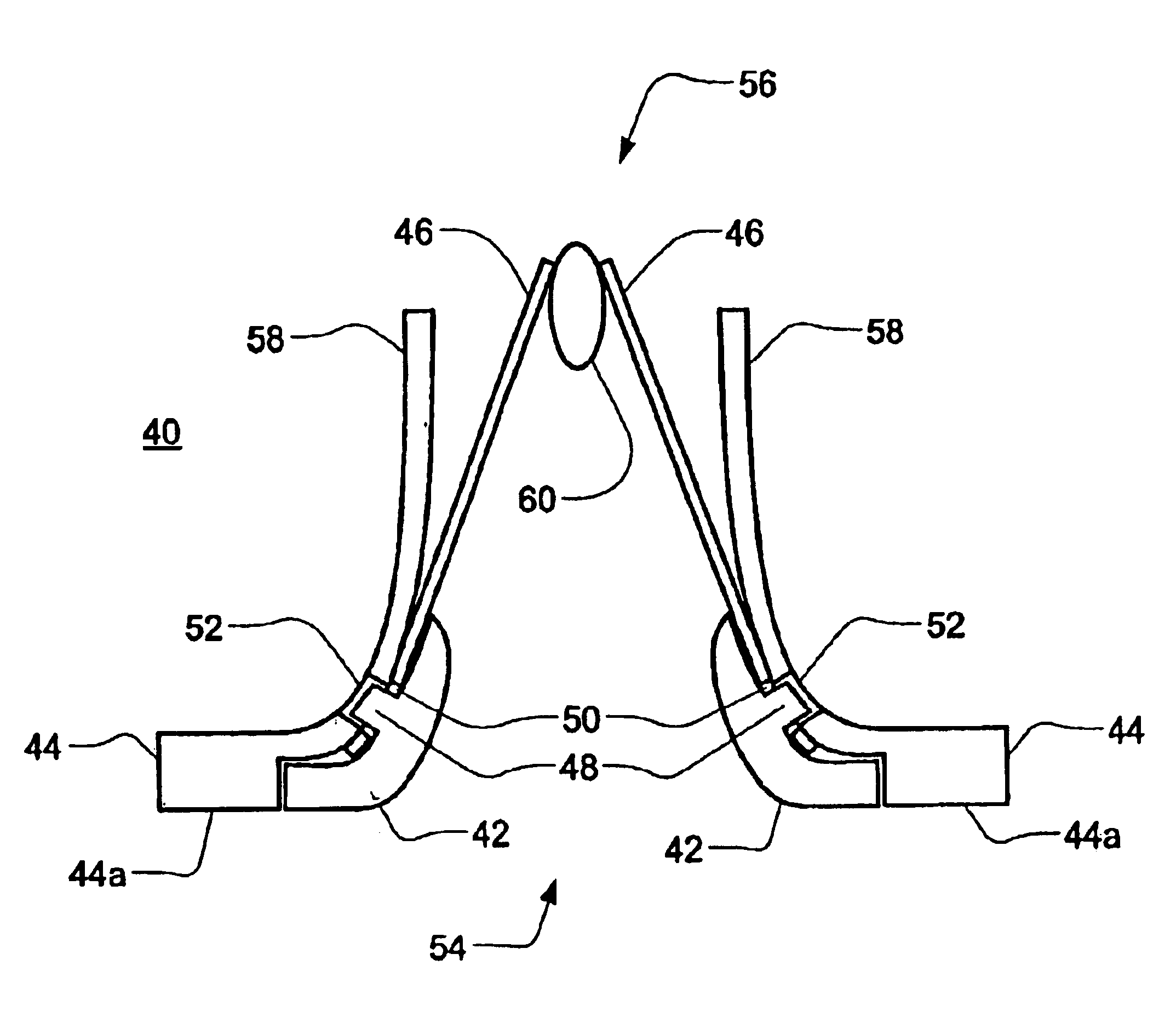
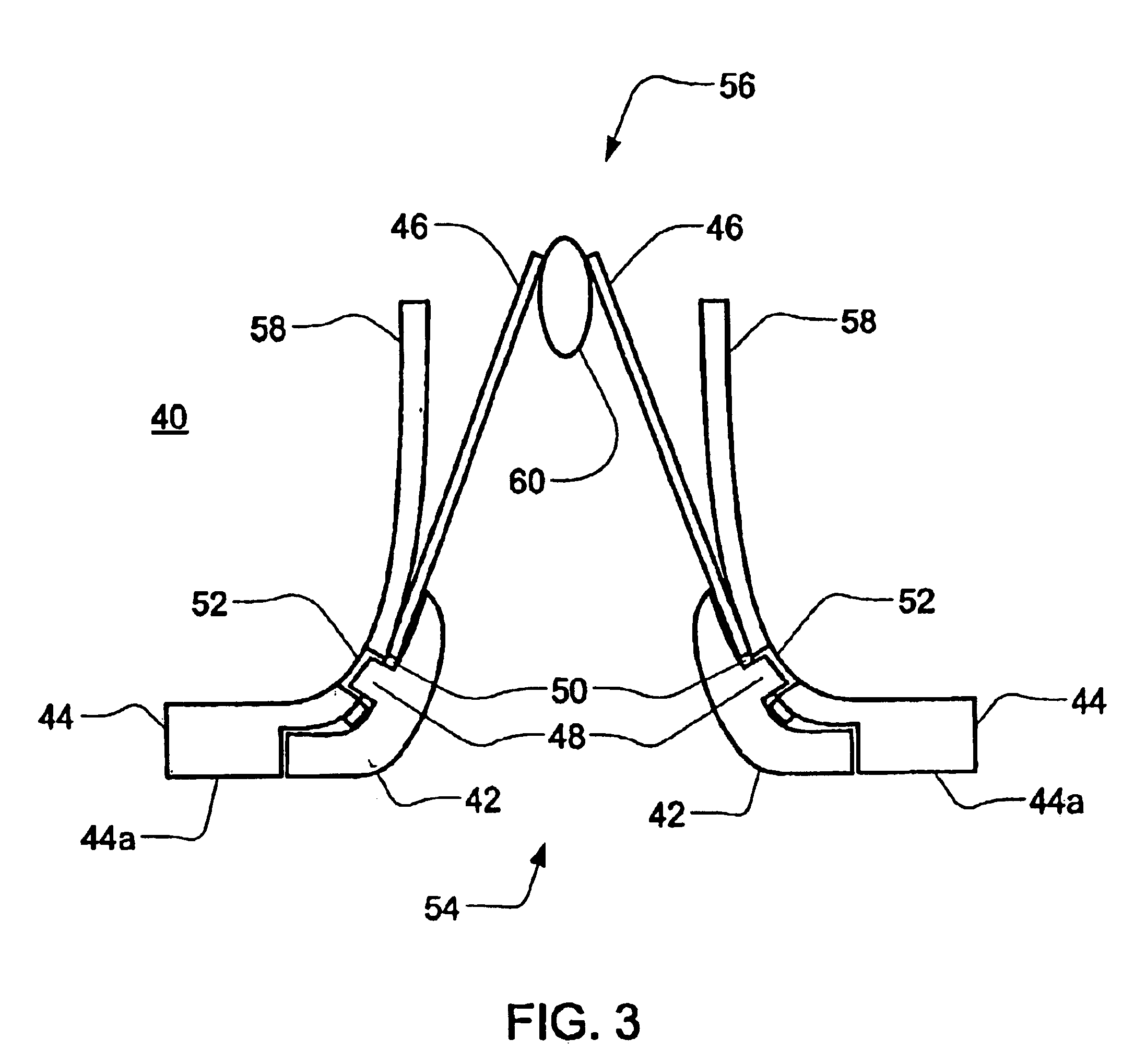
[0020]The reed valve assembly 40 of the present invention, as shown in FIG. 3, includes a reed cage 42, a retainer 44, and reed petals 46. The retainer 44 is independently interlockable with the reed cage 42. As defined herein, independently interlockable is understood to mean that no separate parts are required to connect the retainer 44 to the reed cage 42. As implied by the term interlockable, the retainer 44 and reed cage 42 are separable. The reed petals 46 are removably secured to the reed cage 42.

[0021]In one embodiment, the reed petals 46 are secured to the reed cage 42 with the retainer 44. As shown in FIG. 3, the retainer 44 is a flange 44a, one of several possible embodiments for the retainer 44. Tabs 48 are formed in the reed cage 42. The reed petals 46, with holes 50 formed therein, fit over the tabs 48. The flange 44a is slotted 52 to accept the tabs 48, thereby interlocking the retainer 44 to the reed cage 42 and securing the reed petals 46 in place.

[0022]In one embod...


PUM


Abstract

The reed valve assembly of the present invention includes a reed cage, a retainer, and reed petals. The retainer is independently interlockable with the reed cage. As defined herein, independently interlockable is understood to mean that no additional parts are required to connect the retainer to the reed cage. As implied by the term interlockable, the retainer and reed cage are separable. The reed petals are removably secured to the reed cage. In one embodiment, the reed petals are secured to the reed cage with the retainer.

Description

FIELD OF THE INVENTION[0001]The present invention relates to the field of engine parts. Specifically, the present invention relates to the field of reed valve assemblies. More specifically, the present invention is directed at reed valve assemblies used in 2-stroke motors.BACKGROUND OF THE PRESENT INVENTION[0002]FIG. 1 is an example of a traditional 2-stroke motor reed valve. The reed valve 10 includes a v-shaped base 12, pliable reed petals 14, and stoppers 16. The base is substantially hollow with a plurality of openings covered by the reed petals 14. In operation, air flows into the center of the base 12 and through the openings in the base 12, pushing the reed petals 14 back towards the stoppers 16. When the air reverses flow, the reed petals 14 press firmly against the base, covering the openings and substantially impeding airflow.[0003]One problem with the traditional 2-stroke motor reed valve is wear and tear on the reed petals 14. A reed petal 14 opens and closes 133 times p...

Claims


Application Information

Patent Timeline
Patent Type & Authority Patents(United States)
IPC IPC(8): F01L3/20F01L3/00F16K15/14F16K15/16
CPCF01L3/205Y10T137/7559Y10T137/7839Y10T137/7891
Inventor TASSINARI, STEVEN M.TASSINARI, SCOTT A.
Owner MOTO TASSINARI
Why Eureka
Try Eureka