Fueling system vapor recovery and containment performance monitor and method of operation thereof

a technology of vapor recovery and containment, which is applied in the direction of liquid transfer devices, packaging goods types, liquid handling, etc., can solve the problems of gasoline dispensing facilities (i.e. gasoline stations) often suffering from a loss of fuel to the atmosphere, inadequate reclamation, and substantial amounts of hydrocarbon vapors to the atmosphere, so as to reduce the number of devices

Inactive Publication Date: 2005-04-19
VEEDER ROOT
View PDF119 Cites 30 Cited by
  • Summary
  • Abstract
  • Description
  • Claims
  • Application Information

AI Technical Summary

Benefits of technology

[0020]It is yet another object of the present invention to reduce the number of devices required to determine A / L ratios for individual dispensing points in a fueling facility.

Problems solved by technology

Gasoline dispensing facilities (i.e. gasoline stations) often suffer from a loss of fuel to the atmosphere due to inadequate vapor collection during fuel dispensing activities, excess liquid fuel evaporation in the containment tank system, and inadequate reclamation of the vapors during tanker truck deliveries.
It has been found that even with these measures, substantial amounts of hydrocarbon vapors are lost to the atmosphere, often due to poor equipment reliability and inadequate maintenance.
A low ratio means that vapor is not moving properly through the dispensing nozzle, hose, or other part of the system back to the storage tank, possibly due to an obstruction or defective component.
The proposed regulations also specify an elaborate and expensive monitoring system with many sensors which will be difficult to wire to a common data acquisition system.
When the vapor recovery system produces these elevated pressures, it may force significant amounts of vapor past the pressure relief valve at the end of the storage tank vent pipe or out of other leaky system valves and fittings and into the atmosphere as air pollution.
Vapors produced as a result of dispensing fuel into an ORVR equipped vehicle are collected onboard, and accordingly, are not available to flow through a vapor return passage to an AFS for measurement.
Because the vapor recovery system cannot distinguish between ORVR equipped vehicles and conventional vehicles, the vapor recovery system may be falsely determined to be malfunctioning when an ORVR equipped vehicle is refueled.
Therefore this problem will be become more severe in the coming decades.

Method used


Image

  • Fueling system vapor recovery and containment performance monitor and method of operation thereof
  • Fueling system vapor recovery and containment performance monitor and method of operation thereof
  • Fueling system vapor recovery and containment performance monitor and method of operation thereof

Examples


first embodiment

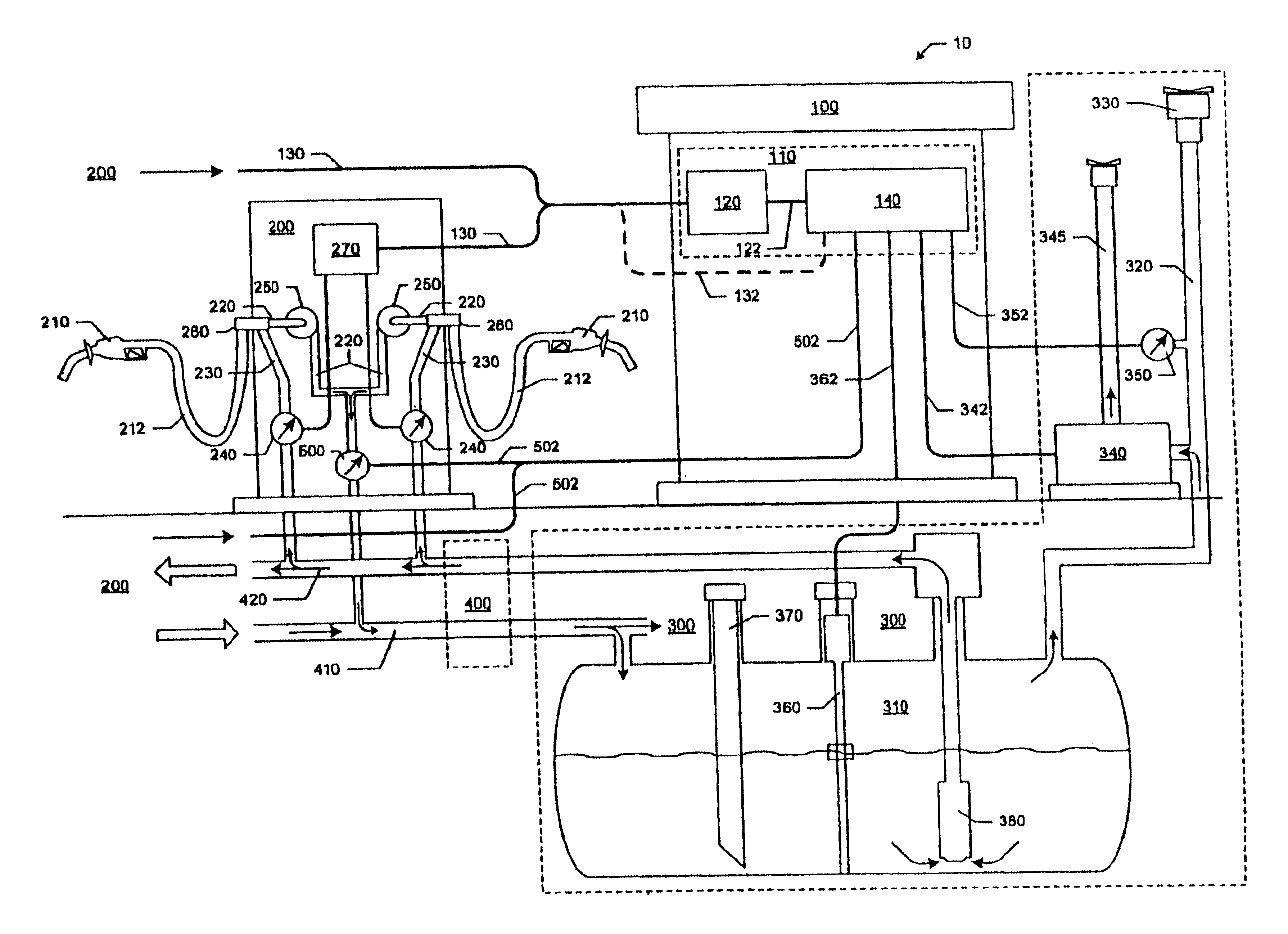
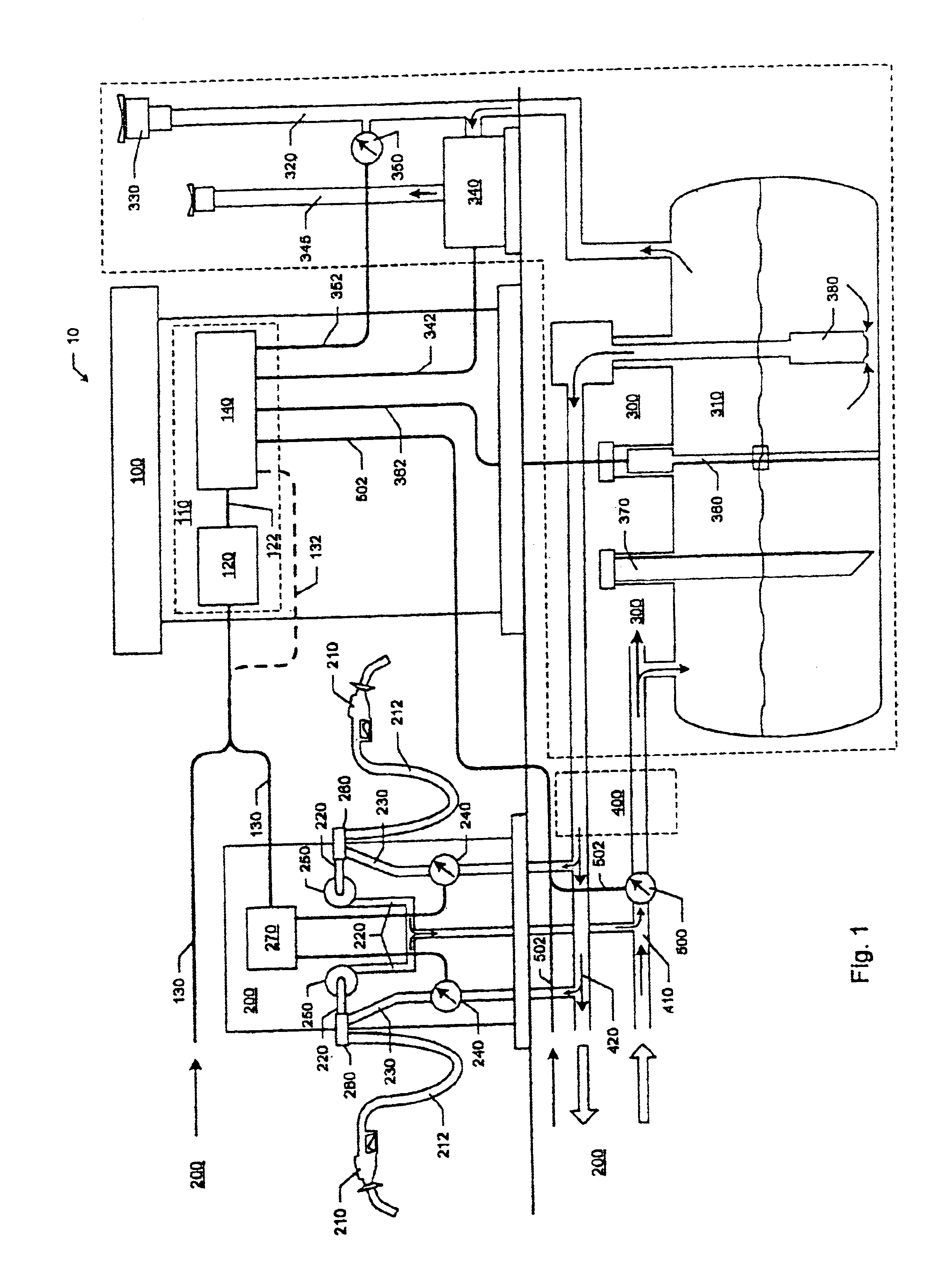
[0037]the invention is described in connection with FIG. 1, which shows a vapor recovery and containment monitoring system for use in a liquid fuel dispensing facility 10. The dispensing facility 10 may include a station house 100, one or more fuel dispenser units 200, a main fuel storage system 300, means for connecting the dispenser units to the main fuel storage system 400, and one or more vapor (or air) flow sensors (AFS's) 500.

[0038]The station house 100 may include a central electronic control and diagnostic arrangement 110 that includes a dispenser controller 120, dispenser current loop interface wiring 130 connecting the dispenser controller 120 with the dispenser unit(s) 200, and a combined data acquisition system / in-station diagnostic monitor 140. The dispenser controller 120 may be electrically connected to the monitor 140 by a first wiring bus 122. The interface wiring 130 may be electrically connected to the monitor 140 by a second wiring bus 132. The monitor 140 may in...
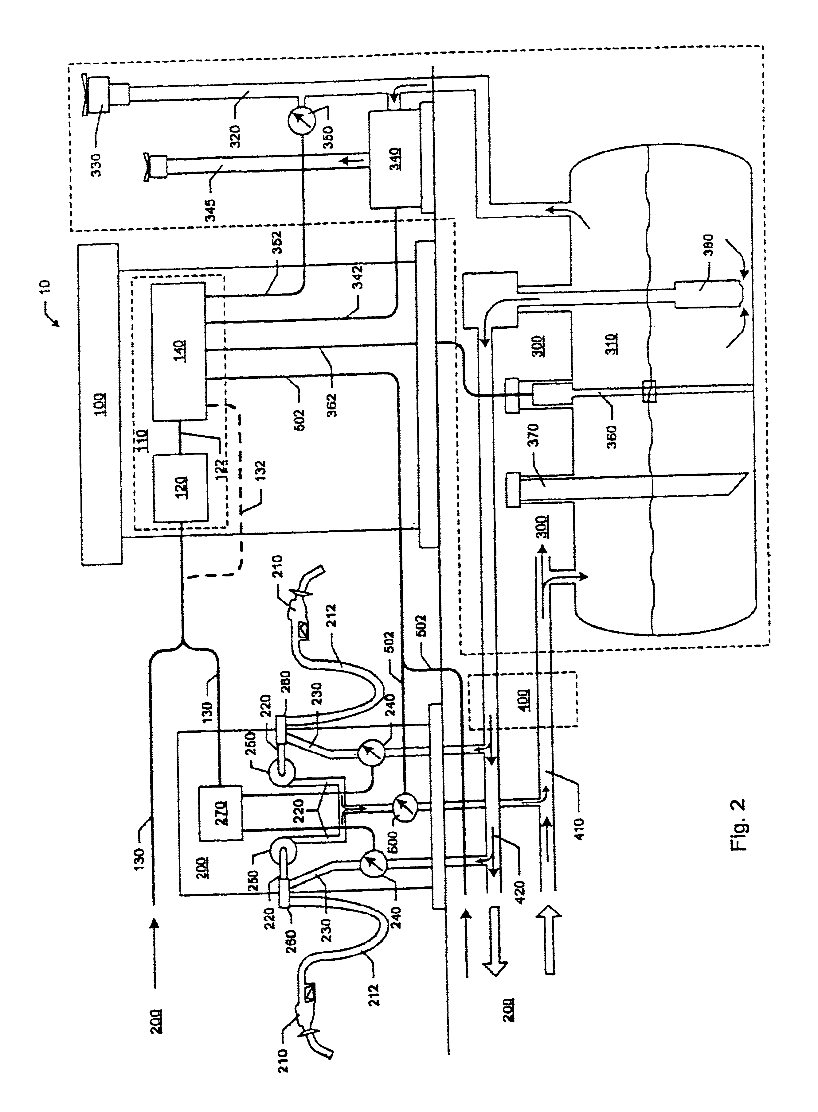
second embodiment

[0046]With reference to the invention shown in FIG. 2, it is appreciated that multiple AFS's 500 could be deployed to measure various groupings of dispensing point 210 vapor flows, down to a minimum of only two dispensing point vapor flows. The latter example may be realized by installing one AFS 500 in each dispenser housing 200, which typically contains two dispensing point's 210 (one dispensing point per dispenser side) or up to 6 dispensing points (hoses) in Multi-Product Dispensers (MPD's) (3 per side). The vapor flows piped through the vapor return passage 220 may be tied together to feed the single AFS 500 in the dispenser housing.

[0047]As stated above, the monitor 140 may connect to the dispenser controller 120, directly to the current loop interface wiring 130 or directly to the liquid fuel dispensing meter 240 to access the liquid fuel flow volume readings. The monitor 140 may also be connected to each AFS 500 at the facility 10 so as to be supplied with vapor flow amount ...

third embodiment

[0090]the invention concerns the use of a single vapor pressure sensor 350 (same as CARB requirement) to actively determine the tightness of the overall vapor containing elements of the facility including the fuel storage system 300, (which includes the vent pipe 320, pressure relief valve 330, etc.), the vapor return pipelines 410, the vapor / liquid splitter 260, the vapor return passages 220, the dispenser hose 212, the nozzle 210, etc. The vapor pressure sensor 350 may be connected anywhere in the fuel storage system 300 or the pipeline system 400, which includes but is not limited to the storage tank 310 vapor-space, the common vapor return pipeline 410, or the storage tank vent pipe 320. The vapor pressure sensor 350 may be used periodically to actively measure the leakage of vapors from the overall system instead of constantly measuring for leakage amount.

[0091]The method in accordance with the third embodiment of the invention may be carried out as follows. The monitor 140 may...


PUM

PropertyMeasurementUnit
thresholdaaaaaaaaaa
pressureaaaaaaaaaa
pressure levelaaaaaaaaaa

Abstract

A method and apparatus for monitoring and determining fuel vapor recovery performance is disclosed. The dispensing of liquid fuel into a tank by a conventional gas pump nozzle naturally displaces a mixture of air and fuel ullage vapor in the tank. These displaced vapors may be recovered at the dispensing point nozzle by a vapor recovery system. A properly functioning vapor recovery system recovers approximately one unit volume of vapor for every unit volume of dispensed liquid fuel. The ratio of recovered vapor to dispensed fuel is termed the A / L ratio, which should ideally be approximately equal to one (1). The A / L ratio, and thus the proper functioning of the vapor recovery system, may be determined by measuring liquid fuel flow and return vapor flow (using a vapor flow sensor) on a nozzle-by-nozzle basis. The disclosed methods and apparatus provide for the determination of A / L ratios for individual nozzles using a reduced number of vapor flow sensors. The disclosed methods and apparatus also provide for the determination of fuel dispensing system vapor containment integrity and the differentiation of true vapor recovery failures as opposed to false failures resulting from the refueling of vehicles provided with onboard vapor recovery systems.

Description

CROSS REFERENCE TO RELATED APPLICATIONS[0001]This application claims priority and is a continuation of U.S. patent application Ser. No. 09 / 725,727 filed Nov. 30, 2000, which is incorporated by reference herein in its entirety, now U.S. Pat. No. 6,622,757, which claims priority on U.S. Provisional Patent Application Ser. No. 60 / 168,029, filed on Nov. 30, 1999, entitled “Fueling System Vapor Recovery Performance Monitor,” on U.S. Provisional Patent Application Ser. No. 60 / 202,054, filed on May 5, 2000, entitled “Fueling System Vapor Recovery Performance Monitor,” and on U.S. Provisional Patent Application Ser. No. 60 / 202,659, filed on May 8, 2000, entitled “Method of Determining Failure of Fuel Vapor Recovery System.”FIELD OF THE INVENTION[0002]The present invention relates to a vapor recovery performance monitor for use in connection with gasoline dispensing facilities.BACKGROUND OF THE INVENTION[0003]Gasoline dispensing facilities (i.e. gasoline stations) often suffer from a loss of...

Claims


Application Information

Patent Timeline
Patent Type & Authority Patents(United States)
IPC IPC(8): B67D5/01B67D5/04B67D7/04
CPCB67D7/0486B67D7/0496G01M3/26F02M25/0872G01M3/02F02M25/0809
Inventor HART, ROBERT P.LUCAS, RICHARD K.
Owner VEEDER ROOT
Why Eureka
Try Eureka