Apparatus for adjusting position of mirror in projector

Inactive Publication Date: 2005-04-19
LG ELECTRONICS INC
View PDF9 Cites 38 Cited by
  • Summary
  • Abstract
  • Description
  • Claims
  • Application Information

AI Technical Summary

Benefits of technology

[0016]Therefore, it is an object of the present invention to provide an apparatus for adjusting the position of a mirror in projector, which can easily adjust an illuminating system and improve quality of image and production efficiency by a

Problems solved by technology

As a result, the quality of image formed on a screen is deteriorated which is sometimes shown on a screen, for example, yellow color appears on the right and le

Method used


Image

  • Apparatus for adjusting position of mirror in projector
  • Apparatus for adjusting position of mirror in projector
  • Apparatus for adjusting position of mirror in projector

Examples


Embodiment Construction

[0027]The present invention will now be described in detail in connection with preferred embodiments with reference to the accompanying drawings. For references like reference characters designate corresponding parts throughout several views.

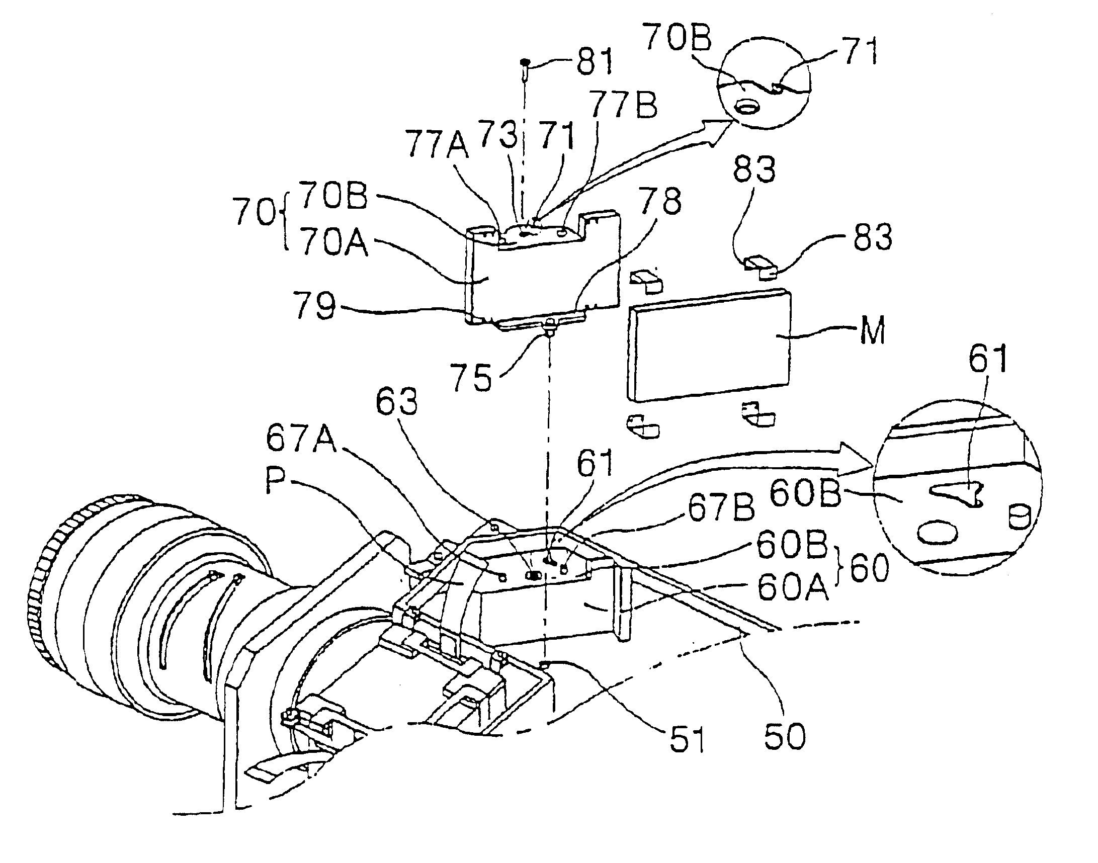
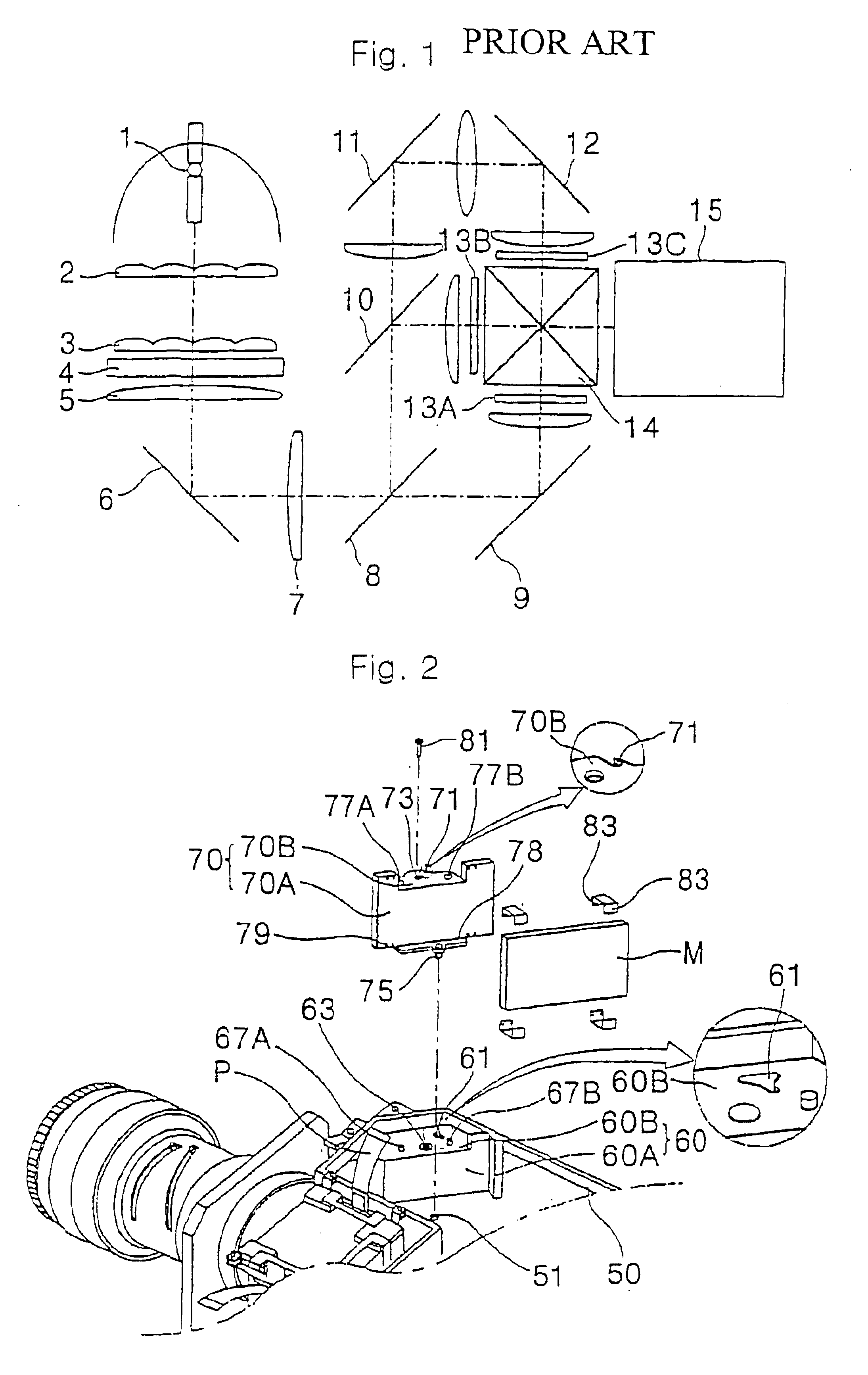
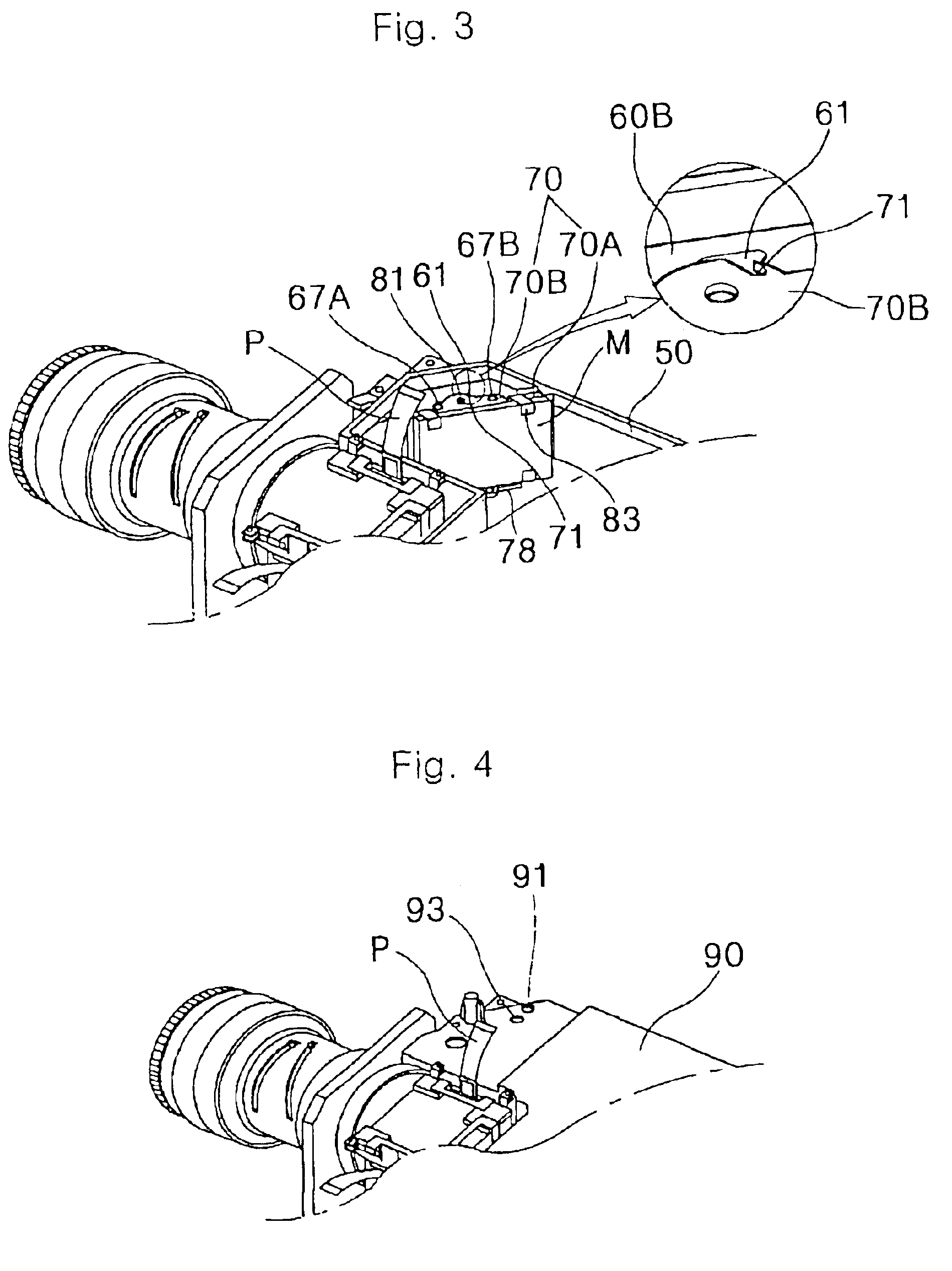
[0028]FIG. 2 is an exploded perspective view of an apparatus for adjusting a position of a mirror in a projector according to the present invention, FIG. 3 is a perspective view showing an assembled state of the apparatus to adjust position of a mirror in a projector according to the present invention, FIG. 4 is a perspective view showing the state that an optical case cover is covered to the state of FIG. 3, and FIG. 5 is a perspective view showing s state of adjusting the position of the mirror using a driver in the apparatus to adjust position of a mirror in projector.

[0029]The apparatus for adjusting the position of the mirror in the projector in accordance with the present invention has an improved installation structure to allow adjustment...


PUM


Abstract

Disclosed is an apparatus to adjust position of a mirror in projector. The mirror position adjusting apparatus includes a mirror, a mirror plate on which the mirror is seated, and a mirror mounting part located in the inside of the projector for adjusting the position of the mirror plate. The mirror position adjusting apparatus according to the present invention can adjust change in position of the mirror occurred due to transformation of plastic by a structure of the projector, which generates intense heat, thereby improving quality of image formed on a screen.

Description

TECHNICAL FIELD[0001]The present invention relates to an apparatus for adjusting a position of a mirror in a projector, and more particularly, to an apparatus for adjusting a position of a mirror in a projector by modifying an installation structure of the mirror in a projector illuminating system.BACKGROUD ART[0002]Recently, as spread of personal computers has been increased, a demand for an LCD (Liquid Crystal Display) projector, which adopts an LCD as an image display panel, is on an increasing trend. The most important part for controlling an image quality in the LCD projector is an illuminating system of an optical engine part for diffusing and collecting light.[0003]Referring to FIG. 1, the LCD projector illuminating system will be described as follows.[0004]First, while light emitted from a lamp 1, which is a light source, passes first and second fly eye lenses 2 and 3, unnecessary ultraviolet ray is removed and distribution of luminous intensity becomes uniform.[0005]Thereaf...

Claims


Application Information

Patent Timeline
IPC IPC(8): G03B21/28G03B27/16
CPCH04N9/317G03B21/28G03B27/16
Inventor LEE, BYUNG-HEE
Owner LG ELECTRONICS INC
Why Eureka
Try Eureka