Impeller

Inactive Publication Date: 2005-04-19
FISHER & PAYKEL HEALTHCARE LTD
View PDF22 Cites 49 Cited by
  • Summary
  • Abstract
  • Description
  • Claims
  • Application Information

AI Technical Summary

Benefits of technology

[0003]The assembly of rotors from a number of parts may also require the individual parts to be accurately formed and assembled, in order to reduce imbalance of the completed rotor product.
[0004]It is

Problems solved by technology

A disadvantage of these traditional blowers is the complexity due to the number o

Method used


Image

  • Impeller
  • Impeller
  • Impeller

Examples


Embodiment Construction

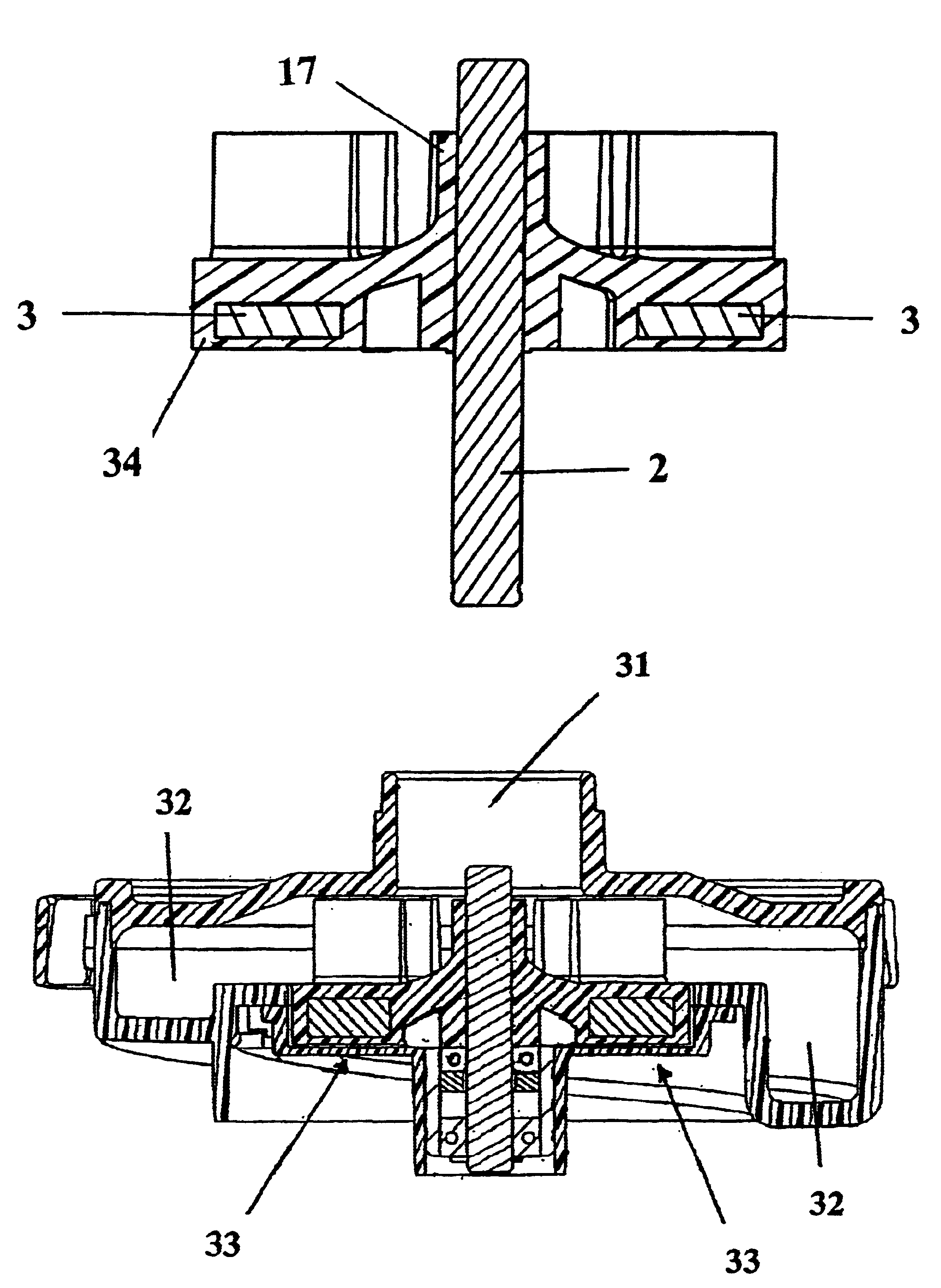
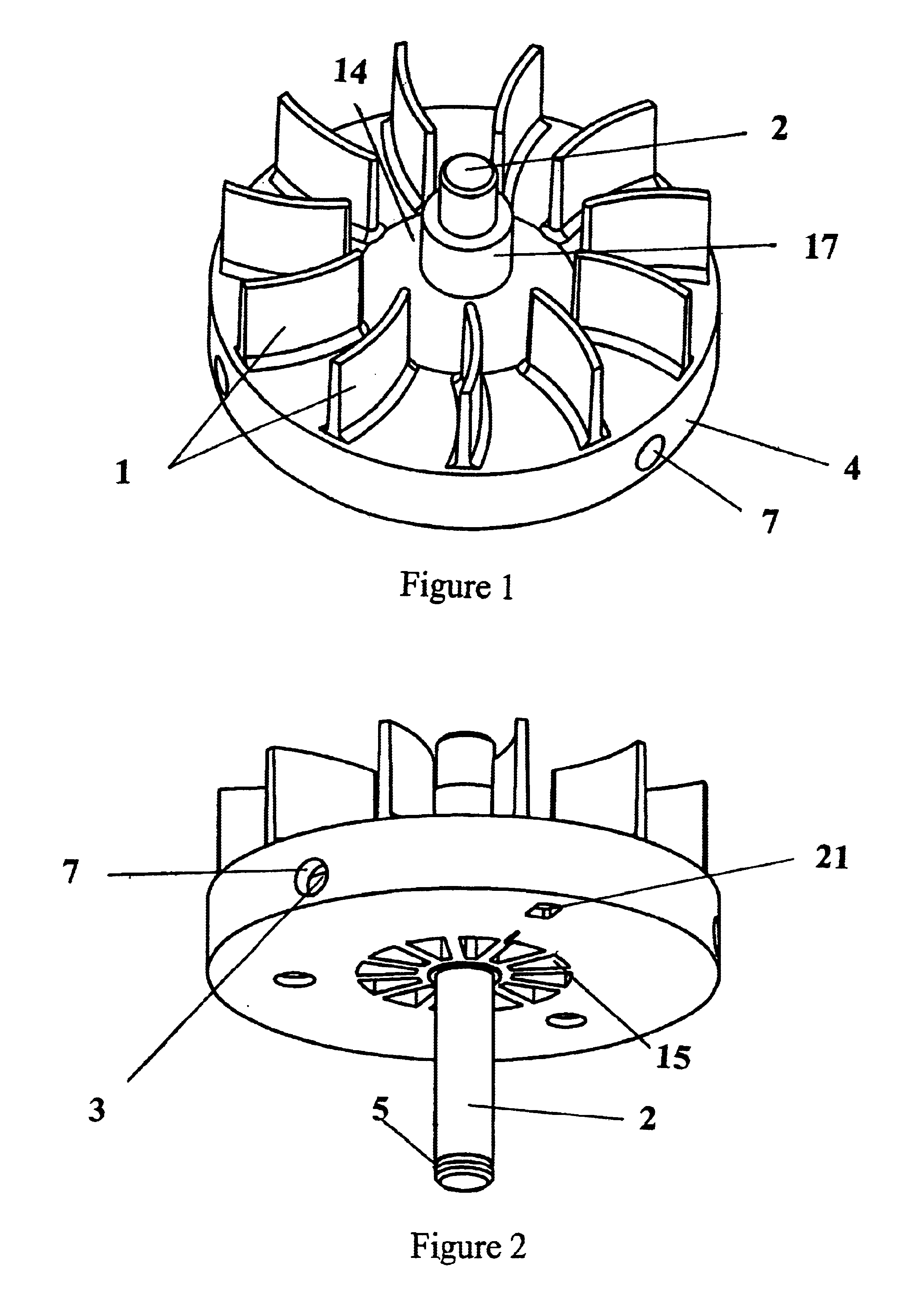
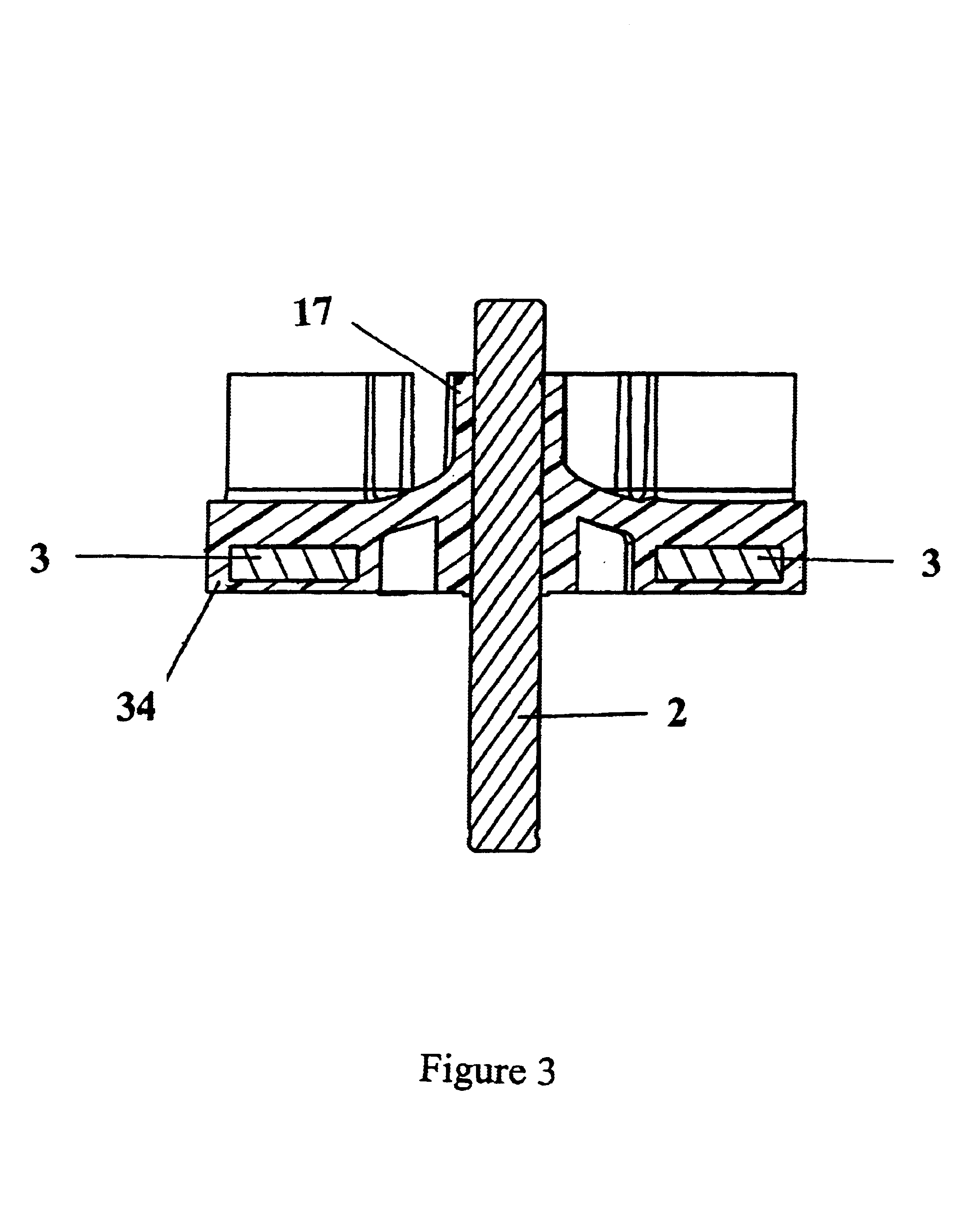
[0044]With reference to FIGS. 1 to 3 a first preferred embodiment of the present invention will be described. The present invention discloses an impeller having a plurality of impeller blades 1 moulded over the permanent magnets of an electric motor rotor. A shaft 2 is also integrally moulded into the rotor assembly during the manufacturing process. The rotor / impeller of the present invention is suitable for use in a pressurised gases supply device such as a CPAP blower. It is also envisaged that the rotor / impeller according to the present invention may provide advantages for any blower / fan application.

[0045]FIG. 12 shows an impeller according to a first preferred embodiment of the present invention installed in a blower housing. Air enters through inlet port 31 where it is blown through the outlet volute 32. Arrows 33 show the position where a commutated stator goes in order to provide a torque to the rotor.

[0046]The resulting assembly is a compact, one piece combined rotor and imp...


PUM


Abstract

An impeller includes a plastic disc, an annular array of vanes, a rotation support and regions of permanently magnetisable material. The plastic disc has an upper face and a lower face. The vanes are spaced around the periphery of the disc and extend from the upper face of the plastic disc. The rotation support is axially located and aligned through the disc. The regions of permanently magnetisable material encapsulated within said plastic disc for the formation of an annular array of magnetic poles.

Description

BACKGROUND TO THE INVENTION[0001]The present invention relates to fan impellers and methods of manufacturing and balancing impellers. In particular the present invention relates to improvements in the manufacture and balancing of impellers wherein the rotor body and impeller are integrally formed.SUMMARY OF THE PRIOR ART[0002]In traditional blower assemblies, an impeller is driven by a motor coupled to it. A disadvantage of these traditional blowers is the complexity due to the number of parts which need to be assembled and thus may contribute significantly to cost.[0003]The assembly of rotors from a number of parts may also require the individual parts to be accurately formed and assembled, in order to reduce imbalance of the completed rotor product.SUMMARY OF THE INVENTION[0004]It is an object of the present invention to provide an impeller for a blower, which will at least go some way towards improving on the above or which will at least provide the industry with a useful choice....

Claims


Application Information

Patent Timeline
IPC IPC(8): B29C45/14F04D25/06F04D25/02F04D13/06F04D29/28F04D29/22F04D29/18
CPCB29C45/14065F04D13/0606F04D25/0653F04D29/2222F04D29/281B29L2031/087Y10T29/49996Y10T29/4998Y10T29/49995Y10T29/49325Y10T29/49316Y10T29/49764F04D29/662
Inventor MAKINSON, IAN DOUGLASPOTHARAJU, SUBBARAODICKINSON, PHILIP JOHN
Owner FISHER & PAYKEL HEALTHCARE LTD
Why Eureka
Try Eureka