Non-foreshortening intraluminal prosthesis

a prosthesis and non-foreshortening technology, applied in the field of intraluminal prosthesis, can solve the problems of stent breakage, dislocation of the lumen of the stent, etc., and achieve the effect of facilitating accurate sizing and deployment, and reducing the time needed for medical procedures

Inactive Publication Date: 2005-04-19
ENDOSYST
View PDF26 Cites 103 Cited by
  • Summary
  • Abstract
  • Description
  • Claims
  • Application Information

AI Technical Summary

Benefits of technology

[0010]It is another object of the present invention to provide an intraluminal prosthesis that provides increased support throughout the prosthesis while minimizing the potential for stent kink or breakage at certain regions along the stent.
[0011]It is yet another object of the present invention to provide an intraluminal prosthesis that minimizes the potential for in-stent restenosis.
[0012]In order to accomplish the objects of the present invention, there is provided a stent having a plurality of cells disposed about the circumference of the stent, with at least one cell having a plurality of struts that are connected together to form the cell. At least one strut has a portion that compensates for foreshortening of the struts during expansion of the stent.
[0014]Thus, the stent according to the present invention maintains a consistent length in both its fully compressed and fully expanded states, and in all states between its fully compressed and fully expanded states. As a result, the stent according to the present invention facilitates accurate sizing and deployment, thereby simplifying, and possibly reducing the time needed for, the medical procedure.

Problems solved by technology

Unfortunately, there are certain drawbacks associated with providing flexible connecting members that have areas of inflection.
Second, curved areas of inflection on these connecting members may cause distortion of the lumen of the stent when the stent is twisted or experiences angulation in the longitudinal direction.
Third, the connecting members form an area of weakness in the stent structure which may encourage kink of the stent at the site with flexion or angulation, or which in extreme circumstances may lead to stent breakage after experiencing repetitive stress.

Method used


Image

  • Non-foreshortening intraluminal prosthesis
  • Non-foreshortening intraluminal prosthesis
  • Non-foreshortening intraluminal prosthesis

Examples


Embodiment Construction

[0033]The following detailed description is of the best presently contemplated modes of carrying out the invention. This description is not to be taken in a limiting sense, but is made merely for the purpose of illustrating general principles of embodiments of the invention. The scope of the invention is best defined by the appended claims.

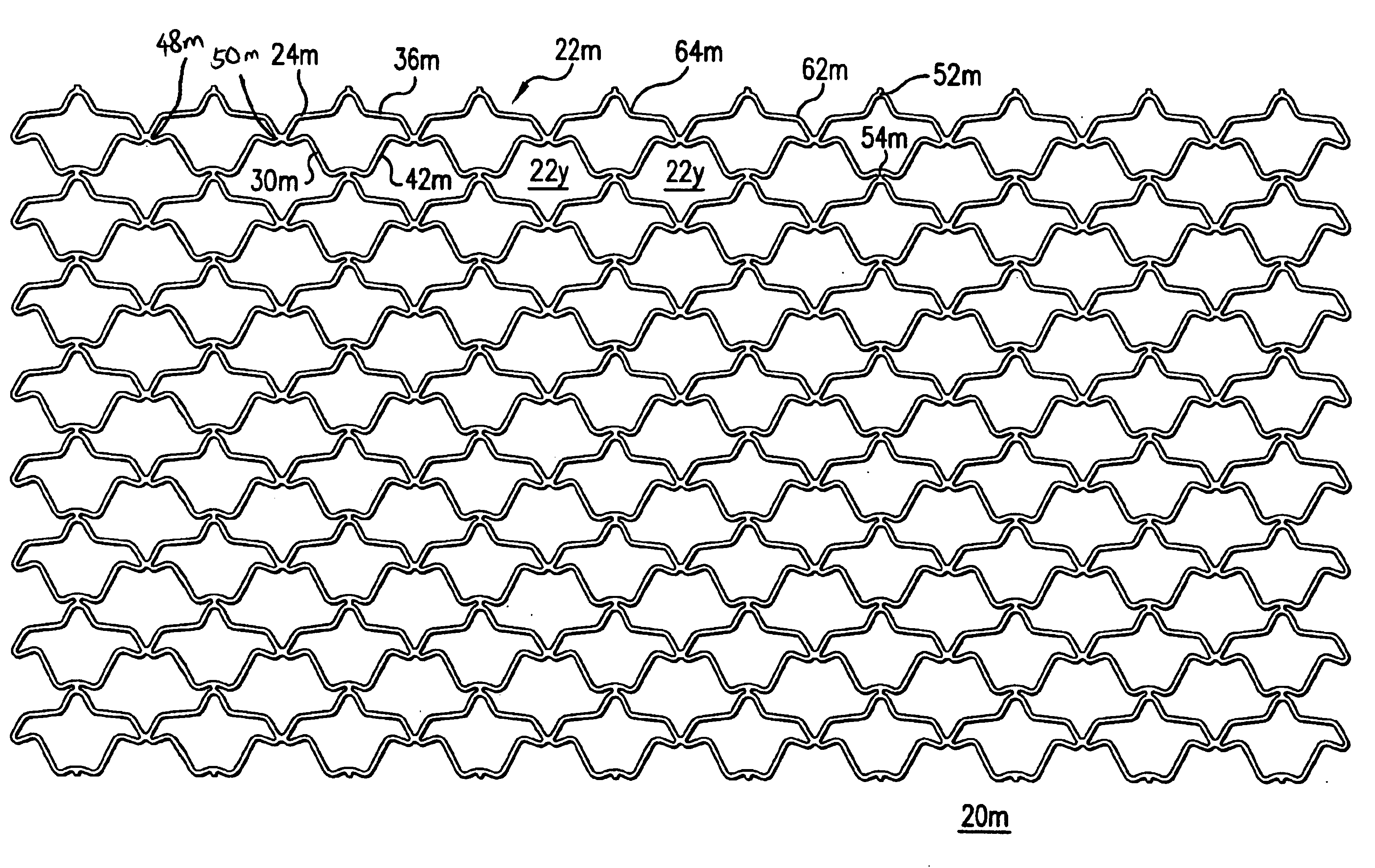
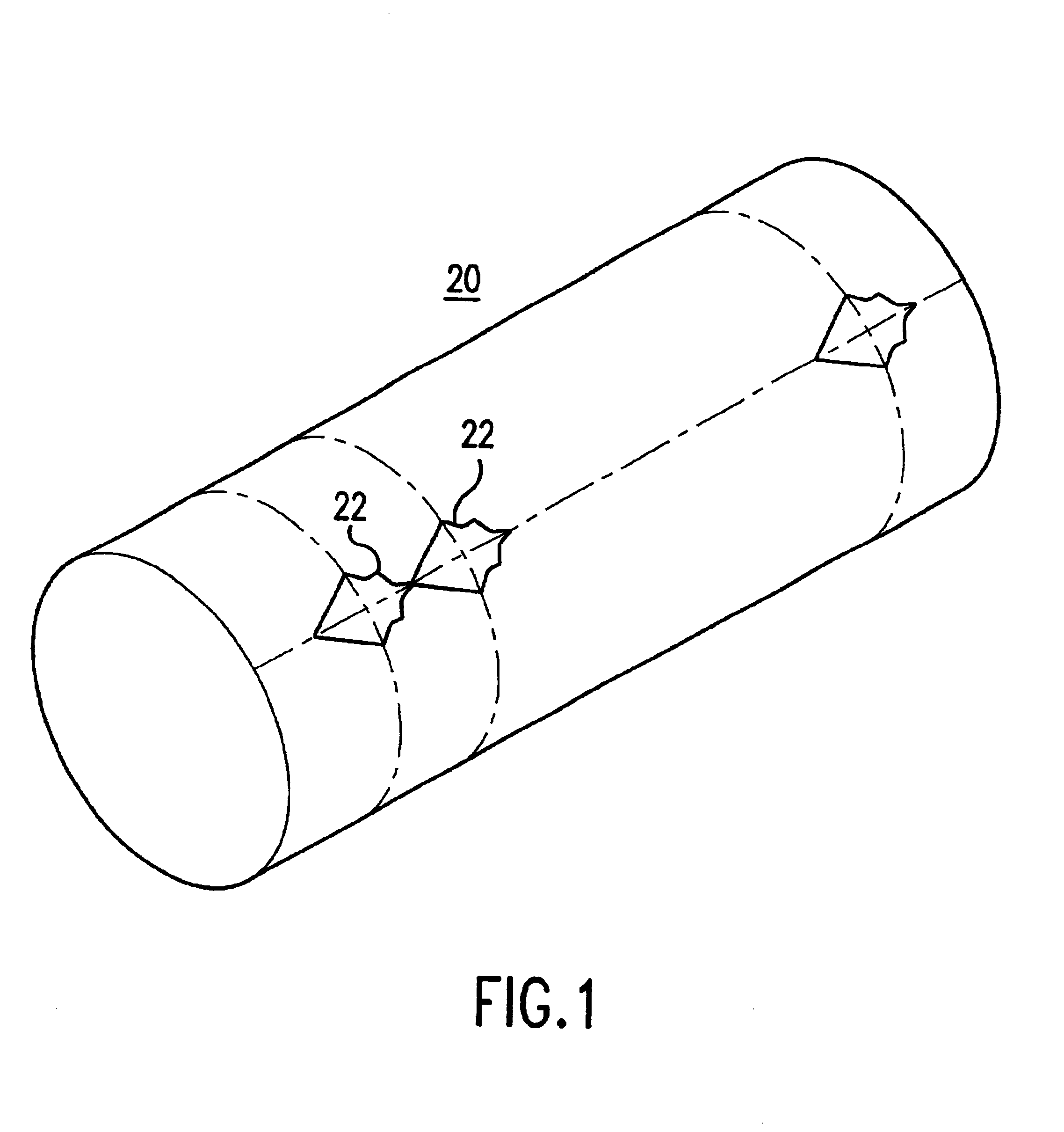
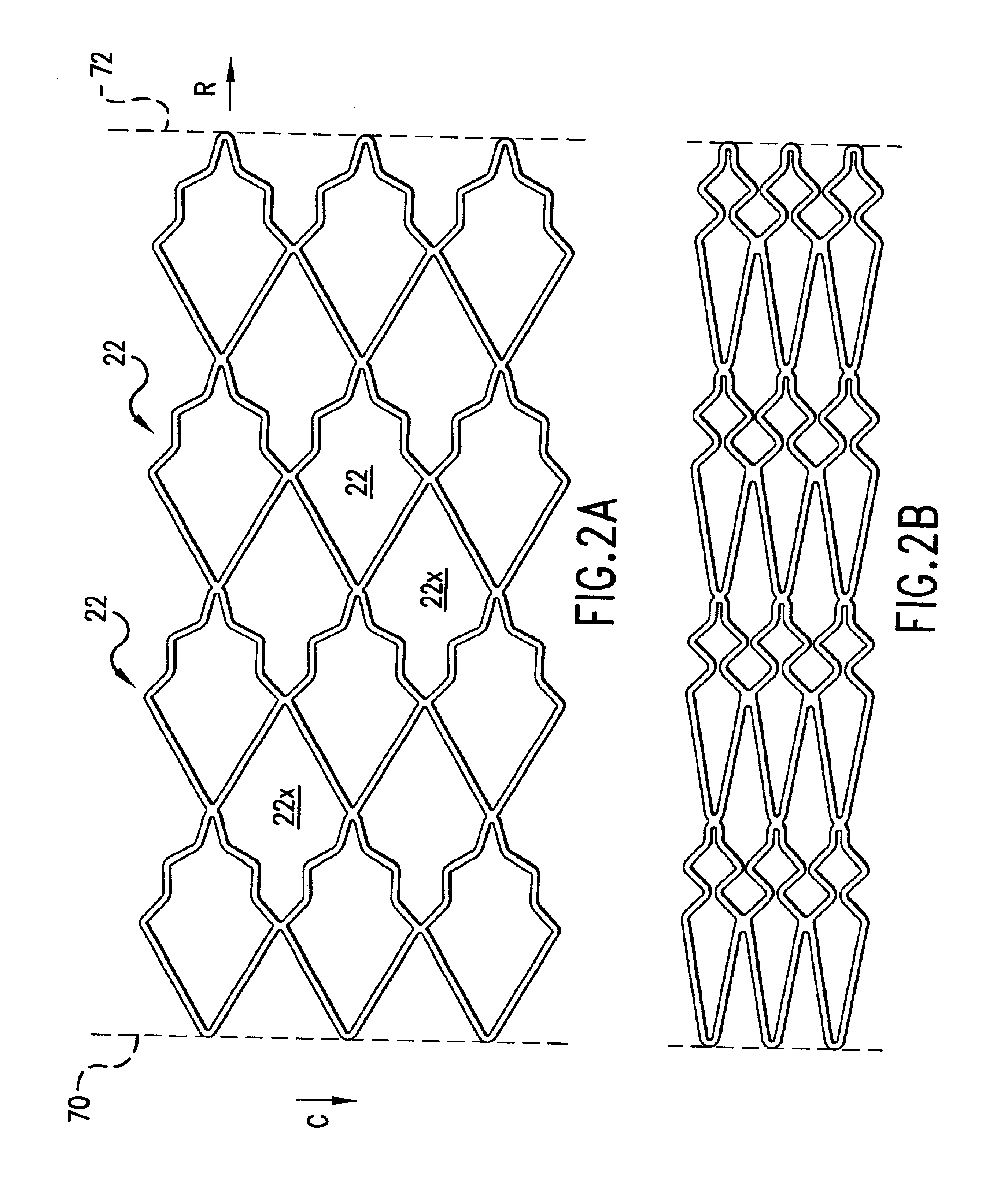
[0034]The intraluminal prosthesis according to the present invention is a stent, although the principles of the present invention are also applicable to other prosthesis such as liners and filters. The stent is delivered to a desired location in the lumen of a body vessel in a compressed state, and is then deployed by expanding it to its expanded state. The stent maintains substantially the same length in both its fully compressed and fully expanded states.

[0035]The stent according to the present invention can be a self-expanding stent, or a stent that is radially expandable by inflating a balloon or expanded by an expansion member, or a stent tha...


PUM


Abstract

A stent has a plurality of cells disposed about the circumference of the stent, with at least one cell having a plurality of struts that are connected together to form the cell. At least one strut has a portion that compensates for foreshortening of the struts during expansion of the stent.

Description

RELATED CASES[0001]This is a divisional application of U.S. Ser. No. 09 / 416,994, filed Oct. 13, 1999, now abandoned, and entitled Non-Foreshortening Intraluminal Prosthesis.BACKGROUND OF THE INVENTION[0002]1. Field of the Invention[0003]The present invention relates to intraluminal prostheses for implantation into a mammalian vessel, and in particular, to intraluminal stents that do not experience foreshortening in the longitudinal direction when the stent is deployed to an expanded state.[0004]2. Description of the Prior Art[0005]Intraluminal prosthesis, such as stents, are commonly used in the repair of aneurysms, as liners for vessels, or to provide mechanical support to prevent the collapse of stenosed or occluded vessels. These stents are typically delivered in a compressed state to a specific location inside the lumen of a vessel or other tubular structures, and then deployed at that location of the lumen to an expanded state. These stents have a diameter in their expanded sta...

Claims


Application Information

Patent Timeline
Patent Type & Authority Patents(United States)
IPC IPC(8): A61F2/06A61F2/84A61F2/90
CPCA61F2/91A61F2/915A61F2002/91508A61F2002/91516A61F2230/0013A61F2002/91533A61F2002/91541A61F2002/9155A61F2002/91558A61F2002/91525
Inventor WHITE, GEOFFREY HAMILTONREDMOND, RUSSELL J.PLYLEY, ALAN K.
Owner ENDOSYST
Why Eureka
Try Eureka