Former for use in paper production

a paper making machine and paper technology, applied in the wet end of the machine, papermaking, textiles and paper, etc., can solve the problems of increasing the degree of difficulty in securing paper quality, and the difficulty in securing paper homogeneity on both sides, so as to reduce the occurrence of paper defects and improve paper quality

Inactive Publication Date: 2005-04-19
VALMET TECH INC
View PDF10 Cites 7 Cited by
  • Summary
  • Abstract
  • Description
  • Claims
  • Application Information

AI Technical Summary

Benefits of technology

[0029]The present invention has been developed in consideration of the above-mentioned problems, and it is therefore an object of the invention to provide a former for use in paper production, which is capable of suppressing the occurrence of paper defects stemming from the landing of the jet or the occurrence of paper defects resulting from drainage to improve the paper quality.

Problems solved by technology

The difficulty of the simultaneous drainage makes it difficult to secure the homogeneity of the surfaces of the paper layer on both sides of paper, and in particular, as the operating speed becomes higher, the degree of difficulty in securing the paper quality increases accordingly.

Method used


Image

  • Former for use in paper production
  • Former for use in paper production
  • Former for use in paper production

Examples


first embodiment

[0107]The paper former (twin-wire former) according to the present invention is constructed as described above, and the function thereof is as follows.

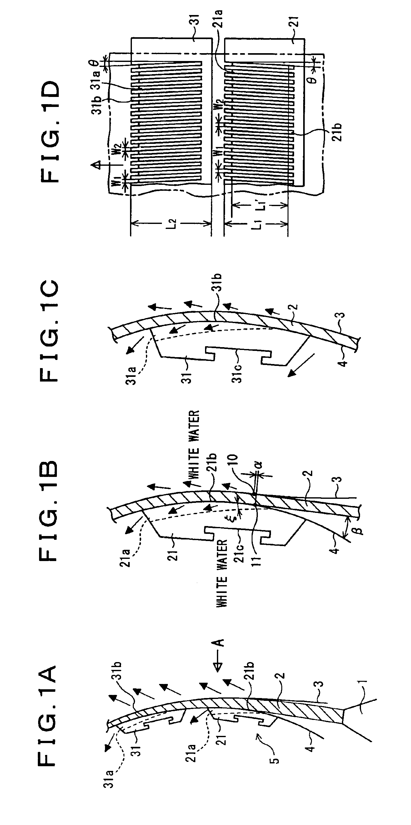
[0108]That is, since an upstream side portion of the wire sliding contact surface 21b in the moving direction of the material jet 2 is formed to have a curved surface configuration inclined to enlarge the paper production gap gradually toward the upstream end thereof, it is possible to lengthen the distance between the two wires 3 and 4 at the upstream side portion of the lead-in blade 21, which facilitates the setting of the landing point 11 of the material jet 2 at a place where the wire 4 comes into sliding contact with the wire sliding contact surface 21b of the lead-in blade 21.

[0109]In addition, when the landing point (#2 wire side material landing point) 11 of the material jet 2 is set on the lead-in blade 21, it is possible to easily reduce the difference α between the landing point 11 and the landing point (#1 wire side mater...

second embodiment

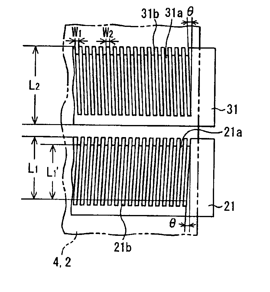
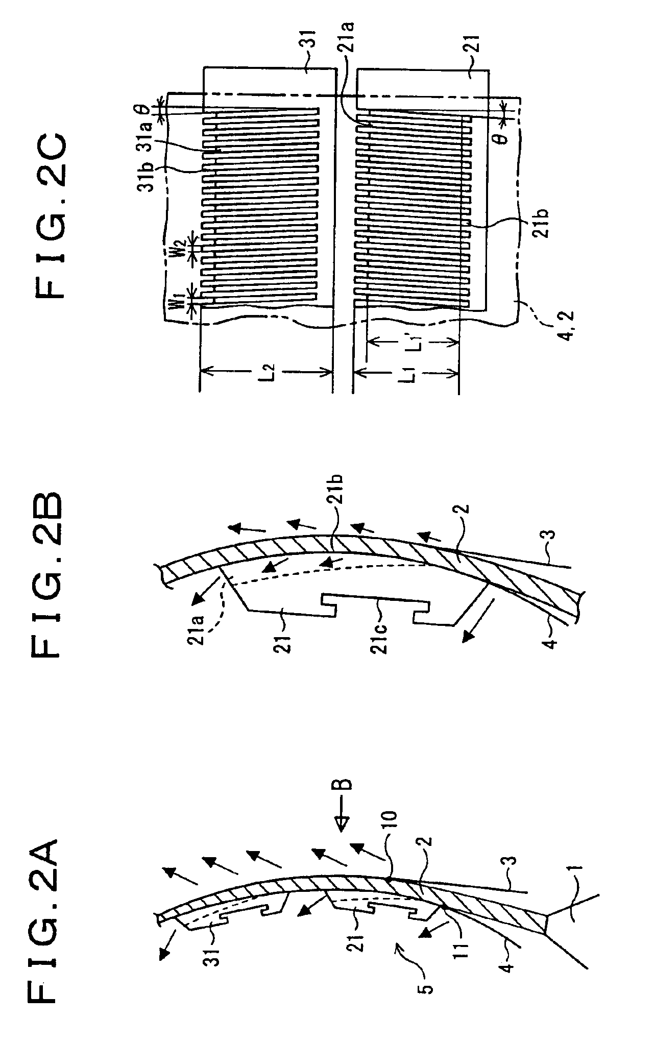
[0128]Furthermore, a description will be given hereinbelow of a second embodiment of the present invention. FIGS. 2A to 2C are illustrations of a paper former (twin-wire former) according to the invention. FIG. 2A is a side elevational view illustratively showing a section in the vicinity of a landing point of a jetted stock, FIG. 2B is an enlarged illustration of an essential part of a first dewatering blade (lead-in blade) portion in FIG. 2A, and FIG. 2C is a front elevational view illustratively showing first and second dewatering blades (an illustration of a section indicated by an arrow B in FIG. 2A).

[0129]In the above-described first embodiment, the landing point 11 of the material jet 2 is set at a portion where the grooves 21a are made on the wire sliding contact surface 21b of the lead-in blade 21. On the other hand, in a case in which the operating speed is not high, or in a case in which the difference α between the landing point 10 on the first wire 3 and the landing poi...


PUM


Abstract

A paper former comprises two wires which converge for defining a paper production gap and a plurality of dewatering blades arranged in the paper production gap in a paper producing direction and brought into sliding contact with one of the two wires so that a stock is dehydrated while being conveyed in a state put in the paper production gap. Each of the plurality of dewatering blades is shaped into a convexly curved surface configuration bent along a traveling direction of the wires and equipped with a wire sliding contact surface brought into sliding contact with said wire for guiding the traveling of said wire, and grooves are made in said wire sliding contact surfaces as a moisture run-off opening for running off moisture developing through the dewatering from the wire side. This paper former thus constructed can suppress the occurrence of paper defects stemming from the landing of a material jet or paper defects stemming from the dewatering property, thus improving the paper quality.

Description

BACKGROUND OF THE INVENTION[0001]1) Field of the Invention[0002]The present invention relates to a forming part of paper making machine, including a twin-wire former, an on-top former and a multilayer former, which is designed to let a stock (material liquid of paper) run through a paper production gap defined between two wires while drying it.[0003]2) Description of the Related Art[0004]A twin-wire former has been known as one of sheet forming apparatus for use in paper machines. This twin-wire former is equipped with two mesh-like wires each shaped into a loop configuration. While a stock travels between these two wires in a state put there between, various types of drainage equipments (extractors) remove the moisture from the stock, thereby gradually forming a fibrous mat, which grows into a web.[0005]For example, FIG. 6 illustratively shows a construction of one example of a twin-wire former. With reference to this illustration, a description will be given here in below of a twi...

Claims


Application Information

Patent Timeline
Patent Type & Authority Patents(United States)
IPC IPC(8): D21F1/48D21F9/00D21F1/52D21F9/02
CPCD21F9/003D21F1/483
Inventor MASUDA, KAZUHIKOIWATA, HIROSHIMATSUMOTO, MASANOBUFUJIKI, KEIICHI
Owner VALMET TECH INC
Why Eureka
Try Eureka