
Low mass generator wedge and methods of using same

Inactive Publication Date: 2005-04-19
SIEMENS ENERGY INC
View PDF25 Cites 17 Cited by
  • Summary
  • Abstract
  • Description
  • Claims
  • Application Information

AI Technical Summary

Benefits of technology

[0005]With the foregoing in mind, the present invention advantageously provides a power generator having a low mass rotor wedge to increase output of the rotor of a power generator and methods of using a wedge to increase power output from a generator. The present invention also advantageously provides a wedge for a power generator which has a substantially reduced mass and is relatively easy to manufacture with little or no decrease in the strength of the wedge. By substantially preserving the strength of the wedge for power generator applications, such as a rotor, the amount of mass reduction can be used to increase the coil size and / or characteristics to thereby enhance power output. For example, when used with a generator rotor, if the wedge strength is held constant, then the total burden that is carried by the wedge is held constant. If material is then removed from the wedge, then the mass of the wedge is reduced, and the mass of the coils and insulation materials can be increased by the mass of the material removed from the wedge. This, therefore, can significantly increase the output of the generator rotor.
[0006]More particularly, a power generator according to the present invention preferably has a stator and a rotor positioned adjacent the stator. The rotor preferably has a plurality of slots formed therein or associated therewith. A plurality of rotor coils are each positioned within a respective one of the plurality of slots. A plurality of rotor wedges are preferably each positioned to retain a respective one of the plurality of rotor coils positioned within a corresponding respective one of the plurality of slots. Each of the plurality of rotor wedges preferably has a wedge body and at least one substantially hollow cavity formed in the wedge body so that the at least one hollow cavity is substantially evenly distributed about a neutral axis of stress applied to the wedge body when in use and so that the neutral axis of stress of the wedge body having the hollow cavity is substantially the same neutral axis of stress of a wedge body having substantially the same shape as the wedge body without the hollow cavity.
[0009]The present invention also advantageously provides a method of using a wedge for a power generator. The method preferably includes increasing the mass of the contents of a slot of a power generator and positioning a wedge having at least one substantially hollow cavity formed therein and longitudinally extending through portions thereof to overlie the contents of the slot and retain the slot contents therein. The increased mass of the contents of the slot is preferably an increase by an amount substantially equal to or less than the mass required to fill the substantially hollow cavity. The method can further include increasing the power output of the power generator responsive to the increased mass of the contents of the slot during operation of the power generator.

Problems solved by technology

Accordingly, the burden that the rotor wedges must carry in retaining the contents of the slot includes the mass of the contents of the slot and the rotor wedge itself.

Method used


Image

  • Low mass generator wedge and methods of using same
  • Low mass generator wedge and methods of using same
  • Low mass generator wedge and methods of using same

Examples


Embodiment Construction

[0026]The present invention will now be described more fully hereinafter with reference to the accompanying drawings which illustrate preferred embodiments of the invention. This invention may, however, be embodied in many different forms and should not be construed as limited to the embodiments set forth herein. Rather, these embodiments are provided so that this disclosure will be thorough and complete, and will fully convey the scope of the invention to those skilled in the art. Like numbers refer to like elements throughout, the prime notation, if used, indicates similar elements in alternative embodiments.

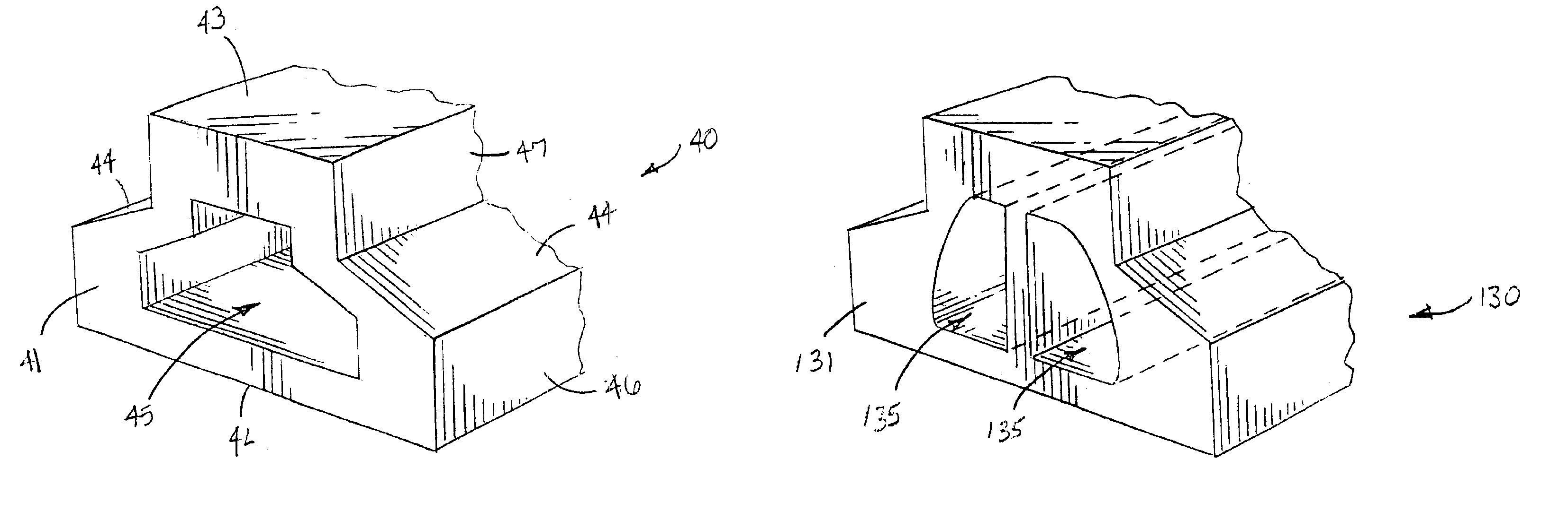
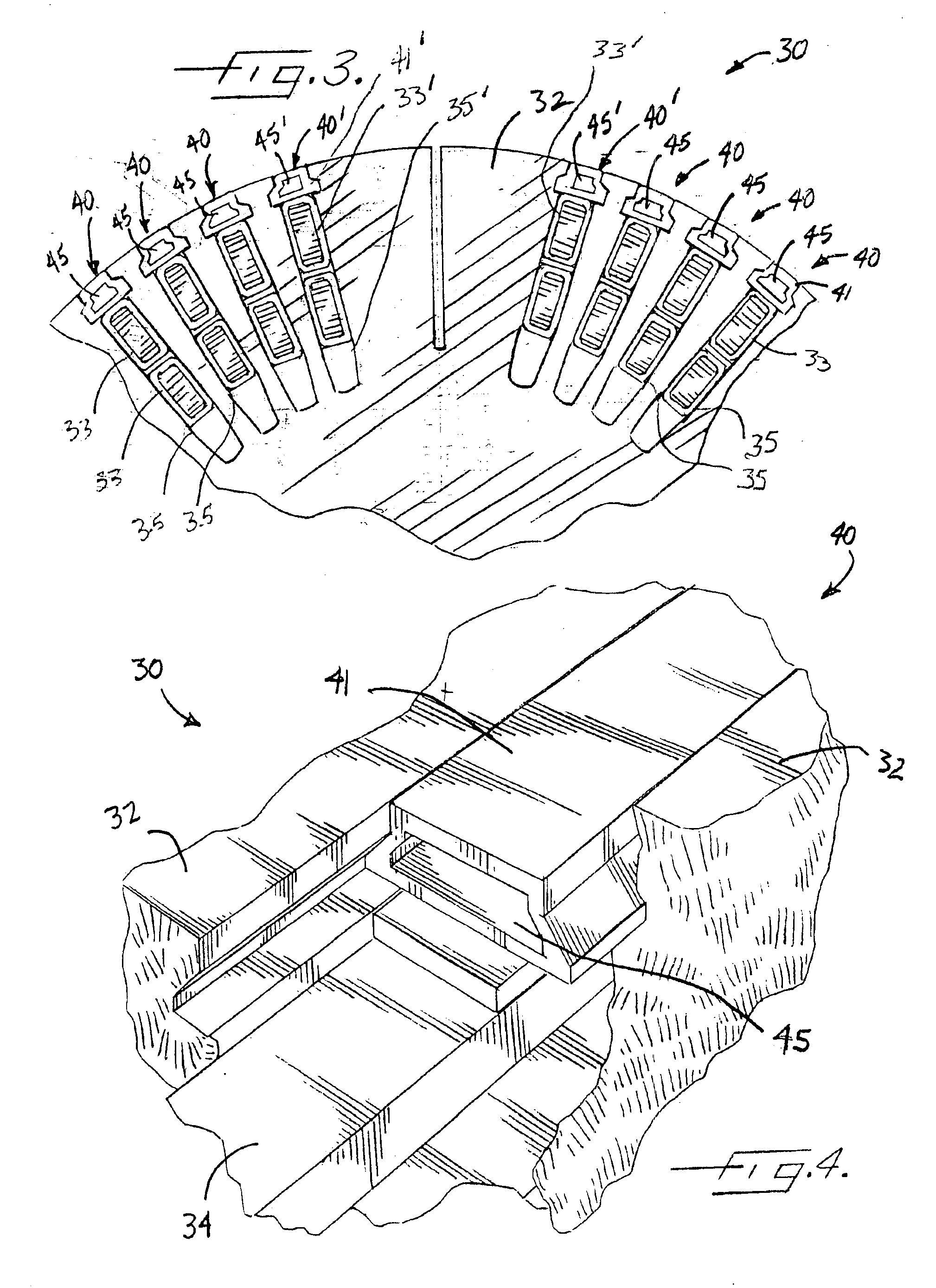
[0027]As perhaps best shown in FIGS. 3-4, a power generator 30 according to the present invention preferably has a stator (not shown) and a rotor 32 positioned adjacent the stator. As understood by those skilled in the art, the stator has a stator core, and the rotor 32 has a rotor shaft positioned to rotate within the stator core and preferably has an axial lead extending axi...


PUM


Abstract

A wedge (40) and methods of using the wedge (40) for a power generator (30) are provided. The wedge (40) preferably has a wedge body (41) and at least one substantially hollow cavity (45) formed in the wedge body (41) so that the at least one hollow cavity (45) is substantially evenly distributed about a neutral axis of stress applied to the wedge body (41) when in use and so that the neutral axis of stress of the wedge body (41) having the hollow cavity (45) is substantially the same neutral axis of stress of a wedge body (41) having substantially the same shape as the wedge body (41) without a hollow cavity. A method of using a wedge (40) preferably includes increasing the mass of the contents of a slot (35) of a power generator (30) and positioning a wedge (40) having at least one longitudinally extending and substantially hollow cavity (45) formed therein and extending throughout major portions of the wedge (40) to overlie the slot (35) and retain the slot contents therein.

Description

FIELD OF THE INVENTION[0001]This invention is related to the power generation industry and, more particularly, to the field of power generators.BACKGROUND OF THE INVENTION[0002]Conventional power generators generate electrical energy by means of induction. Such generators employ a stator core along with a rotor shaft having rotor coils associated therewith to rotate within the stator core in order to convert mechanical energy into electrical energy. The generator rotor conventionally includes a plurality of spaced-apart rotor slots often formed in and extending inwardly from outer peripheries of the rotor, e.g., the rotor body. The rotor slots conventionally have a plurality of electrically-conductive rotor wedges which hold the slot contents, e.g., coils, slot filler, insulating materials, within the slots.[0003]These rotor wedges can have a wide variety of shapes, e.g., a top hat type configuration such as shown in prior art FIG. 1, a Christmas tree type configuration, a dovetail ...

Claims


Application Information

Patent Timeline
IPC IPC(8): H02K3/487
CPCH02K3/487
Inventor KILPATRICK, NEIL LESLIELIGHT, KEVIN M.
Owner SIEMENS ENERGY INC
Features
  • Generate Ideas
  • Intellectual Property
  • Life Sciences
  • Materials
  • Tech Scout
  • Unparalleled Data Quality
  • Higher Quality Content
  • 60% Fewer Hallucinations
Learn More