System and method for measuring transistor leakage current with a ring oscillator

a technology of ring oscillator and leakage current measurement, which is applied in the field of ring oscillator, can solve the problem that leakage current is a significantly larger proportion of power production problems, and achieve the effect of accurately measuring leakage curren

Inactive Publication Date: 2005-04-19
META PLATFORMS INC
View PDF11 Cites 146 Cited by
  • Summary
  • Abstract
  • Description
  • Claims
  • Application Information

AI Technical Summary

Benefits of technology

[0004]Accordingly, what is needed is a system and method for accurately measuring the leakage current of a typical device on a chip. Embodiments of the present invention are directed toward a system an

Problems solved by technology

One of the challenges facing the users and designers of integrated circuits is managing the power produced by a chip.
However, with smaller geometries and reduced operating voltages, the leakage cu

Method used


Image

  • System and method for measuring transistor leakage current with a ring oscillator
  • System and method for measuring transistor leakage current with a ring oscillator
  • System and method for measuring transistor leakage current with a ring oscillator

Examples


Embodiment Construction

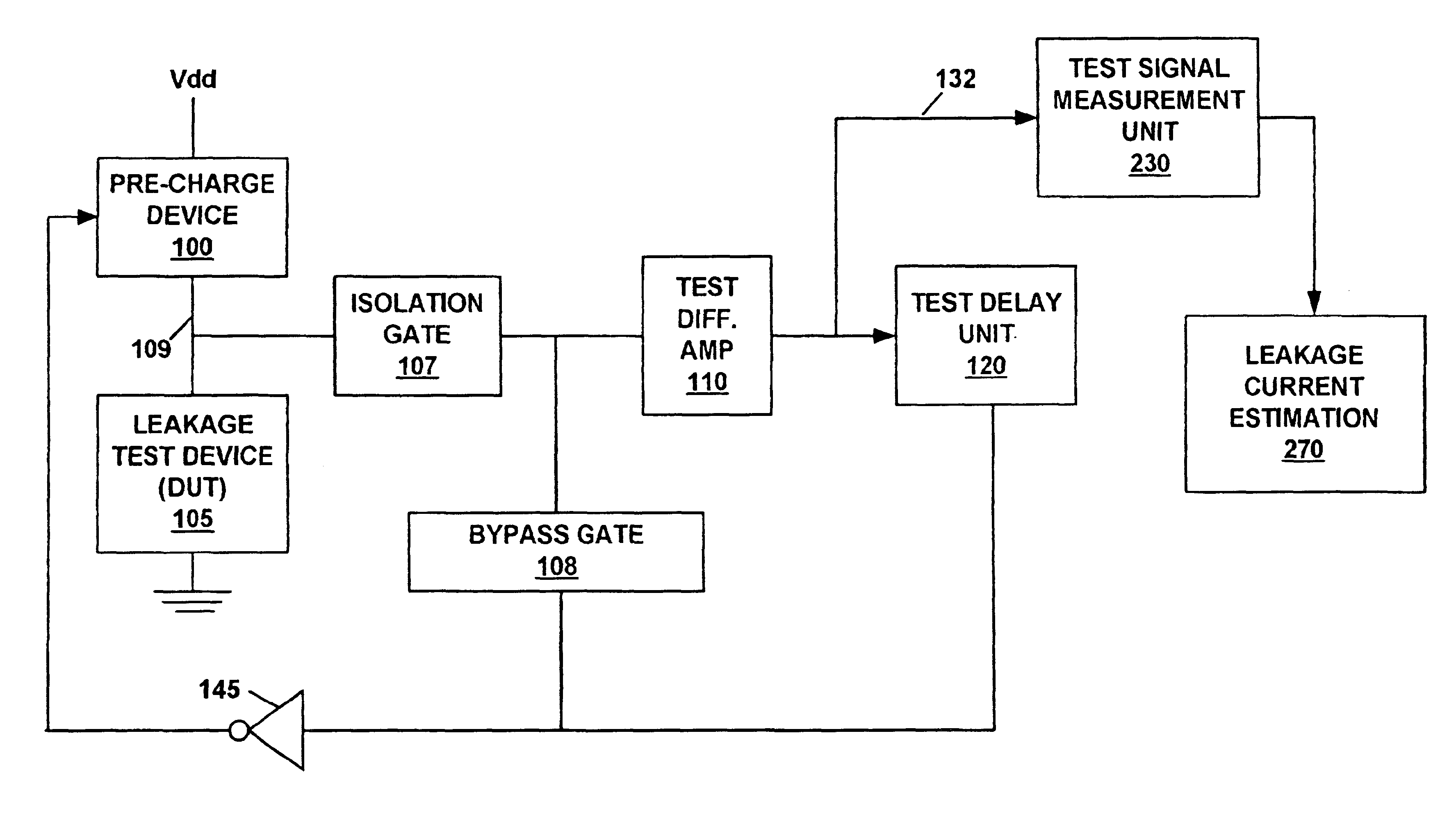
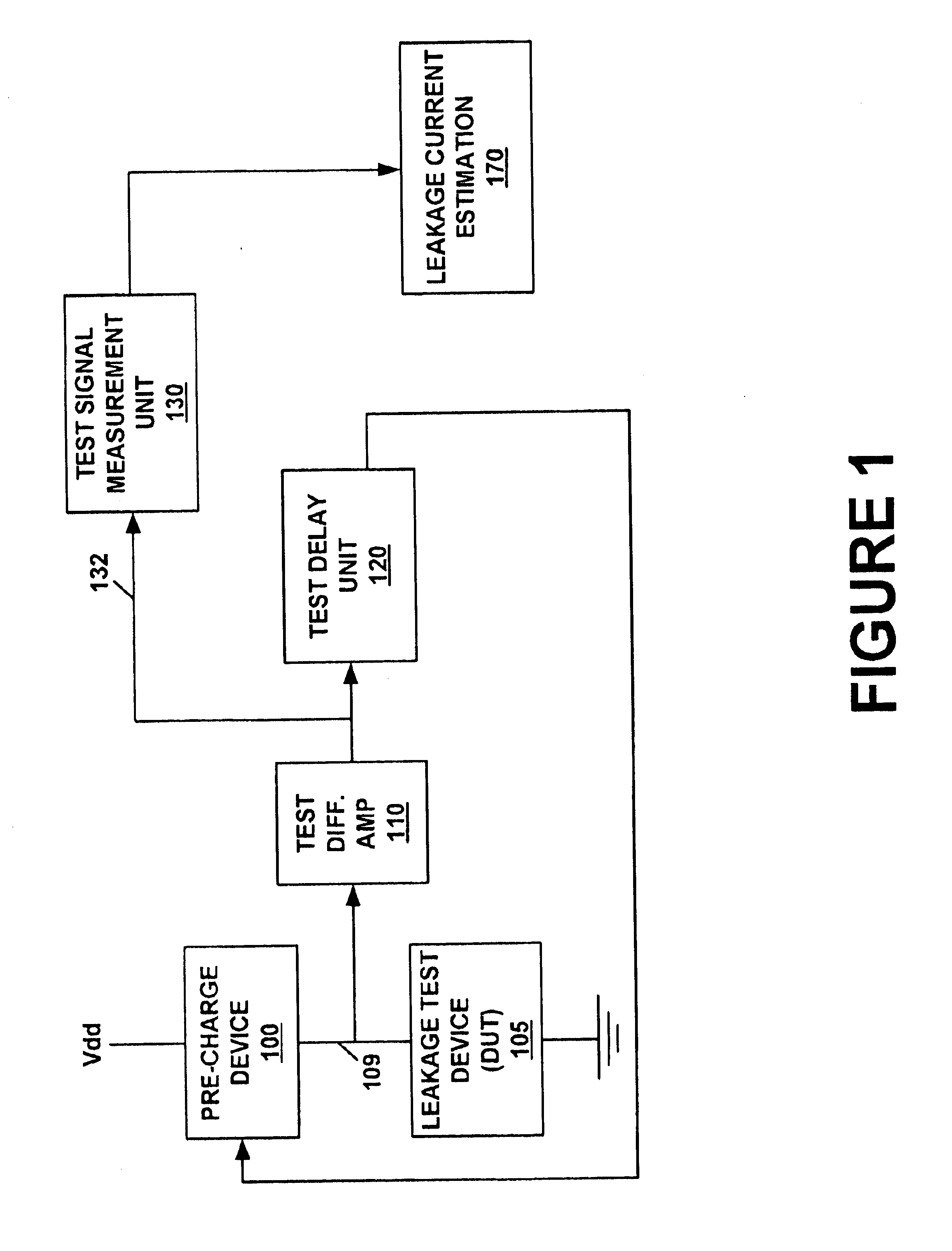
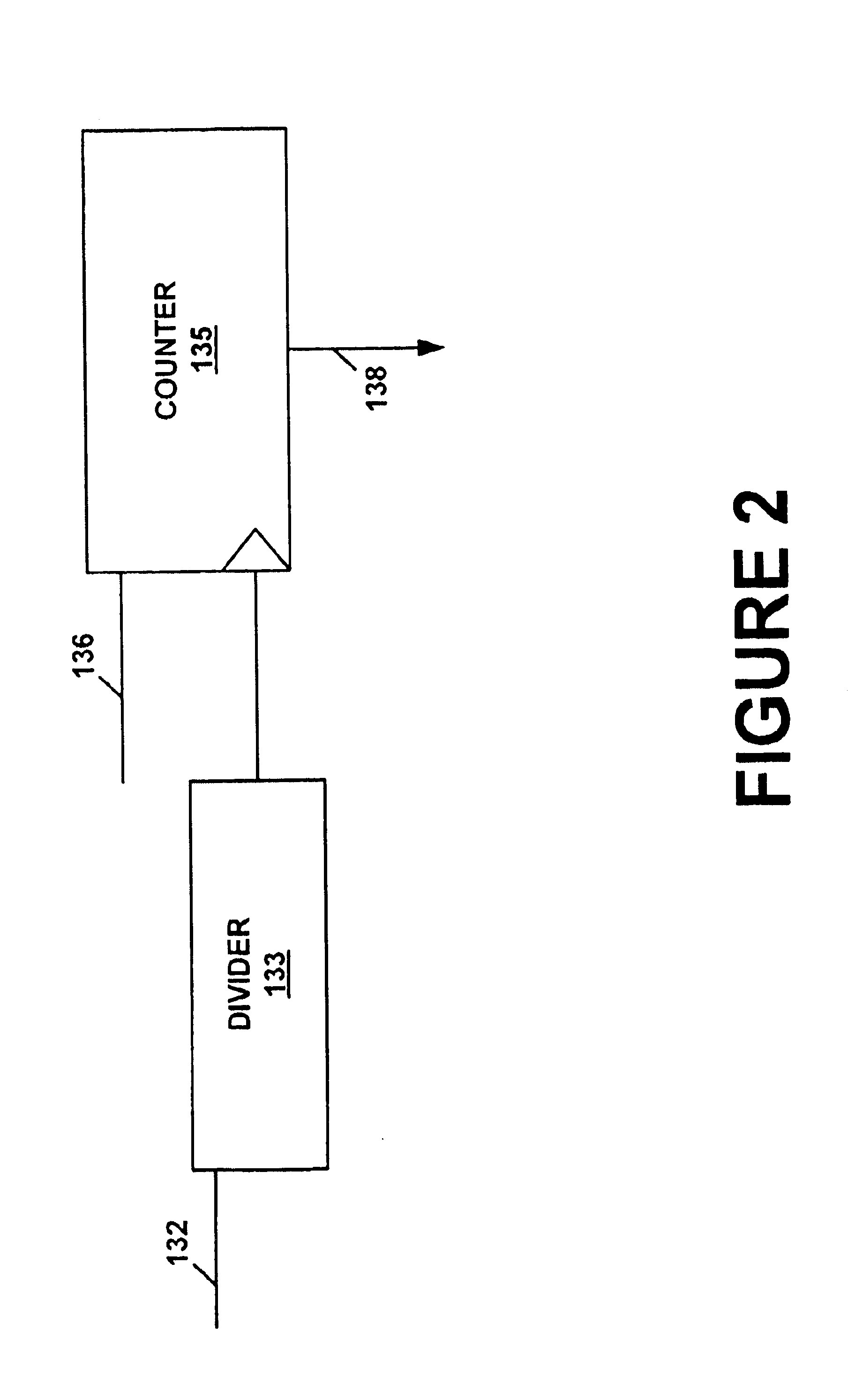
[0030]Reference will now be made in detail to the present embodiments of the invention, examples of which are illustrated in the accompanying drawings. While the invention will be described in conjunction with the present embodiments, it will be understood that they are not intended to limit the invention to these embodiments. On the contrary, the invention is intended to cover alternatives, modifications and equivalents, which may be included within the spirit and scope of the invention as defined by the appended claims. Furthermore, in the following description, for purposes of explanation, numerous specific details are set forth in order to provide a thorough understanding of the present invention. It will be apparent, however, to one skilled in the art, upon reading this disclosure, that the present invention may be practiced without these specific details. In other instances, well-known structures and devices are not described in detail in order to avoid obscuring aspects of th...


PUM


Abstract

A method of measuring the transistor leakage current. In one embodiment, the method involves driving a ring oscillator with a dynamic node driver having a leakage test device biased to an off state to produce a test signal. The test signal is extracted and the frequency is measured. The leakage current is estimated from the measured frequency.

Description

TECHNICAL FIELD[0001]Embodiments of the present invention relate to the field of semi-conductor circuits. More specifically, embodiments of the present invention relate to the field of ring oscillators for measuring characteristics of a semi-conductor device.BACKGROUND ART[0002]One of the challenges facing the users and designers of integrated circuits is managing the power produced by a chip. The power dissipated by a digital chip has two basic sources which are switching current and leakage current. When a gate is switching from one logical value to another, there is a brief period time where current passes through the transistors dissipating power in the form of heat. Historically, this switching current has been the focus of the designer's attention because it was substantially greater than the nominal leakage current that occurred when the gate was not switching and the transistors were “off”.[0003]However, with smaller geometries and reduced operating voltages, the leakage cur...

Claims


Application Information

Patent Timeline
IPC IPC(8): G01R31/26G01R31/27G01R31/28
CPCG01R31/2621G01R31/2884G01R31/27G01R31/52
Inventor SUZUKI, SHINGOBURR, JAMES
Owner META PLATFORMS INC
Why Eureka
Try Eureka