Divide-by-X.5 circuit with frequency doubler and differential oscillator

a technology of frequency doubler and differential oscillator, applied in the field of digital dividers, can solve problems such as the unsatisfactory duty cycle produced by these circuits

Inactive Publication Date: 2005-04-19
DIODES INC
View PDF16 Cites 32 Cited by
  • Summary
  • Abstract
  • Description
  • Claims
  • Application Information

AI Technical Summary

Problems solved by technology

The duty cycle produced by the...

Method used


Image

  • Divide-by-X.5 circuit with frequency doubler and differential oscillator
  • Divide-by-X.5 circuit with frequency doubler and differential oscillator
  • Divide-by-X.5 circuit with frequency doubler and differential oscillator

Examples


Embodiment Construction

[0013]The present invention relates to an improvement in divide by X.5 circuits. The following description is presented to enable one of ordinary skill in the art to make and use the invention as provided in the context of a particular application and its requirements. Various modifications to the preferred embodiment will be apparent to those with skill in the art, and the general principles defined herein may be applied to other embodiments. Therefore, the present invention is not intended to be limited to the particular embodiments shown and described, but is to be accorded the widest scope consistent with the principles and novel features herein disclosed.

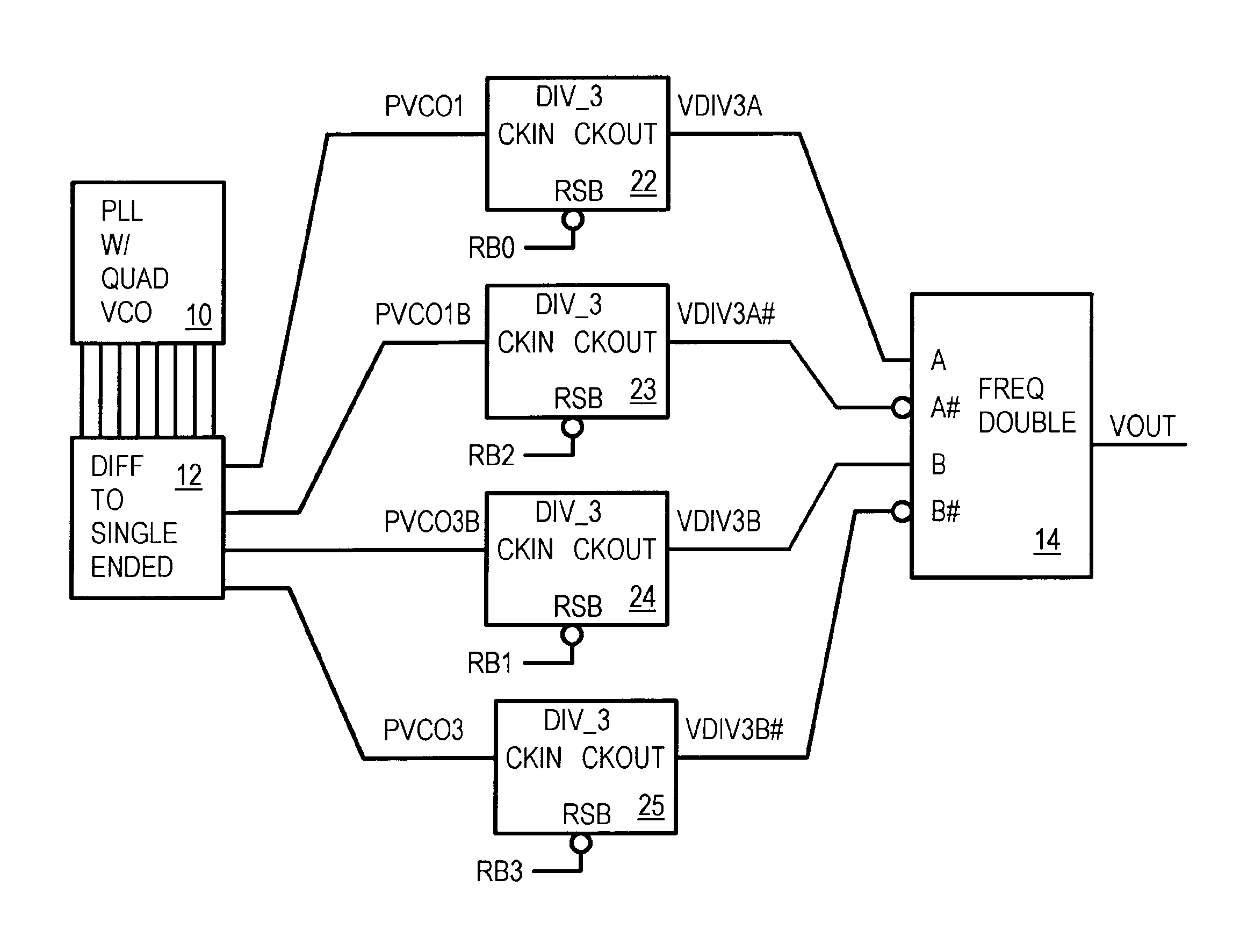
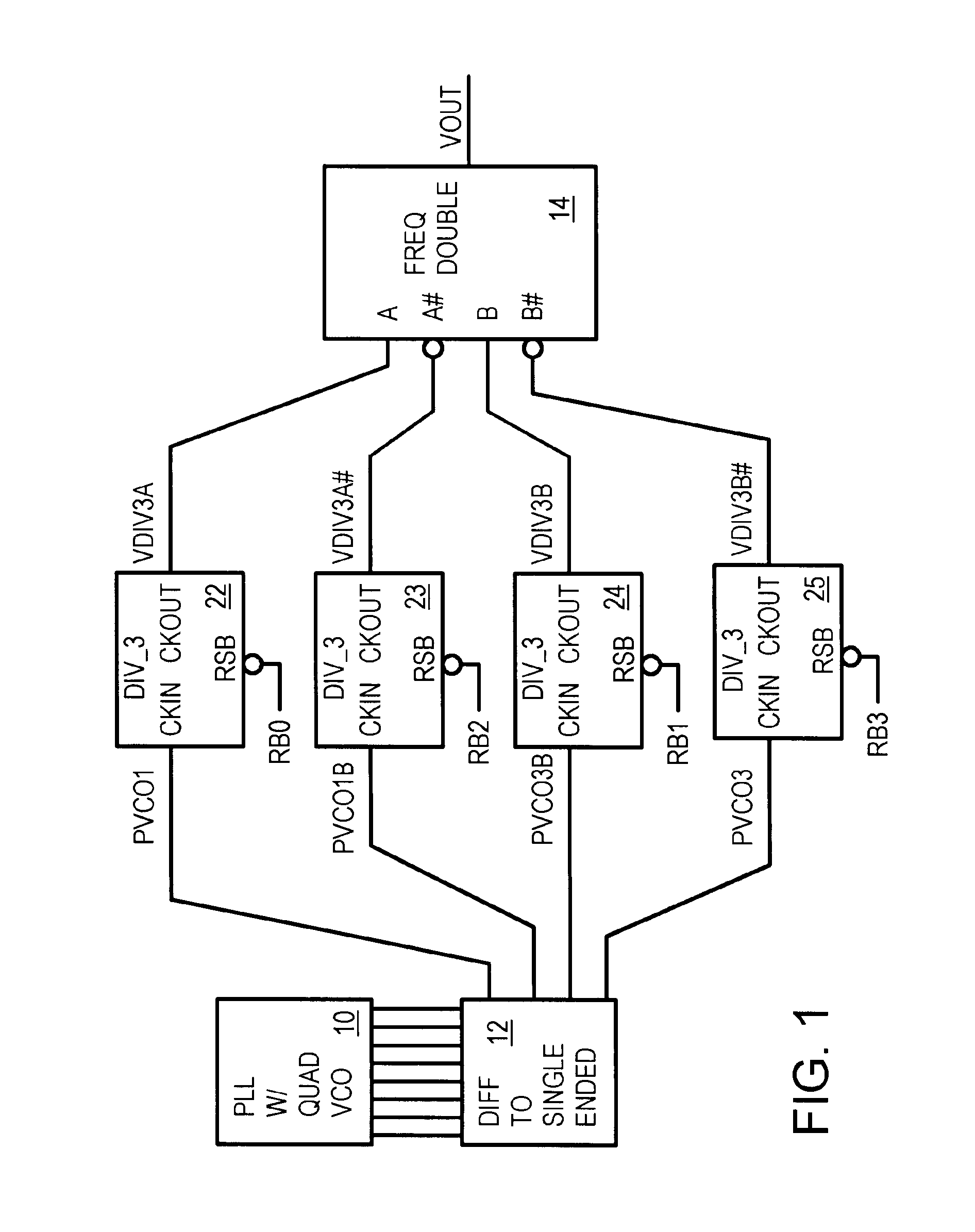
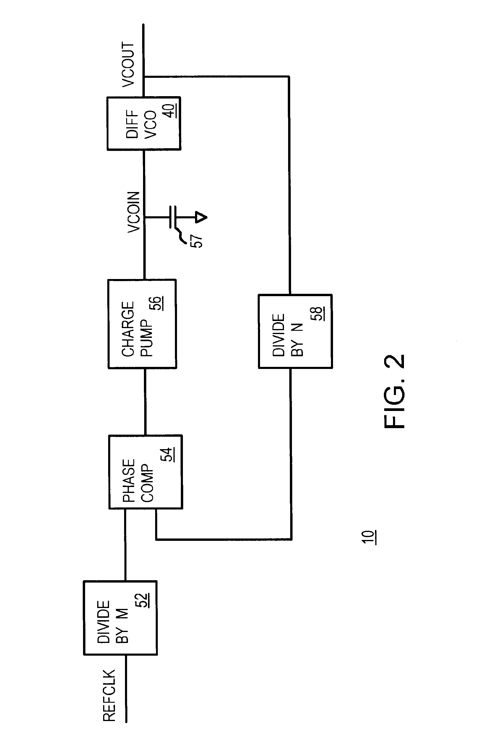
[0014]FIG. 1 is an overall block diagram of a divide by 1.5 circuit. Phase-locked loop (PLL) 10 includes a quadrature voltage-controlled oscillator (VCO) that outputs four phases of clocks having the same frequency, but being offset in phase from one another by 90-degree increments. The multi-phase clocks from PLL 10 have phase...


PUM


Abstract

A divide by X.5 circuit can be implemented as a divided by 1.5 circuit. A phase-locked loop (PLL) has a quadrature voltage-controlled oscillator (VCO) that generates four phases offset at 0, 90, 180, and 270 degrees. Differential signals from the VCO are converted to single-ended VCO clocks that drive four divide-by-3 circuits, each clocked by one of the four phases of the VCO clocks. Resets to the divide-by-3 circuits are staggered to activate each divide-by-3 circuit synchronously with its phase clock. Outputs from the divide-by-3 circuits are applied to a frequency doubler that generates the final clock that is 1.5 times slower than the VCO clocks. The final clock has a near 50%-50% duty cycle.

Description

BACKGROUND OF INVENTION[0001]This invention relates to digital dividers, and more particularly to X.5 divide circuits.[0002]Digital circuits often employ dividers. For example, a clock operating at a higher frequency may be divided by a dividing circuit to generate a lower-frequency clock. Clocked flip-flops can be used when the divisor is a power of two, such as with divide-by-2N circuits, wherein N is a positive integer.[0003]Sometimes a divisor is required that is not a power of two, or not even an integer. For example, a 333 MHz clock may be needed, but only a 500 MHz clock is available. The divisor needed is 500 / 333, or 1.5 (one and a half). Or a 200 MHz clock is needed, requiring a divider circuit with a divisor of 500 / 200=2.5, another non-integer divisor.[0004]A variety of such divide by X.5 circuits have been developed, where X is a positive integer (whole number). The duty cycle produced by these circuits may not always be ideal. Sometimes the output clock's duty cycle is a...

Claims


Application Information

Patent Timeline
IPC IPC(8): H03L7/00H03K23/50H03K23/68H03L7/099H03L7/18
CPCH03K23/502H03L7/18H03L7/0995H03K23/68
Inventor HO, JEFFWING, CHOY KWOK
Owner DIODES INC
Why Eureka
Try Eureka