Power calibration test system and power calibration measurement method

A power calibration and test system technology, applied in the field of measurement, can solve the problems of universality, consistency of effectiveness, and poor accuracy of the power calibration test system in the millimeter wave band, and achieve the effect of improving the generality

Active Publication Date: 2014-09-24
SHANGHAI INST OF MICROSYSTEM & INFORMATION TECH CHINESE ACAD OF SCI
View PDF5 Cites 38 Cited by
  • Summary
  • Abstract
  • Description
  • Claims
  • Application Information

AI Technical Summary

Problems solved by technology

[0006] In view of the above-mentioned shortcomings of the prior art, the purpose of the present invention is to provide a power calibration test system and a calibration measurement method, which a

Method used


Image

  • Power calibration test system and power calibration measurement method
  • Power calibration test system and power calibration measurement method
  • Power calibration test system and power calibration measurement method

Examples


Embodiment 1

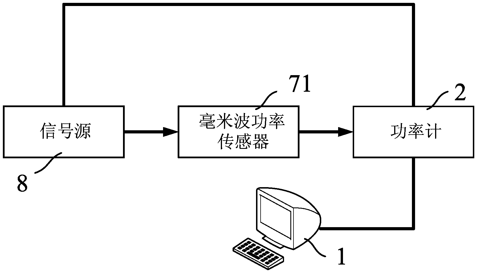
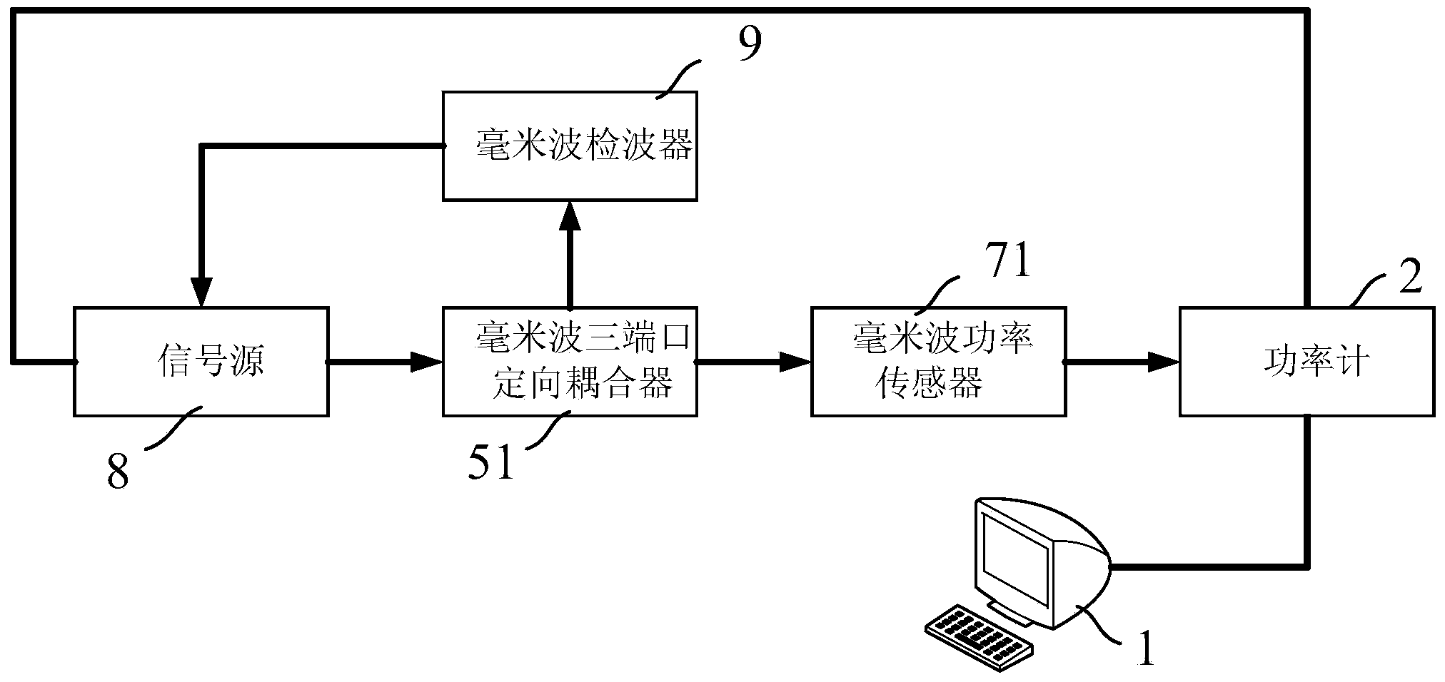
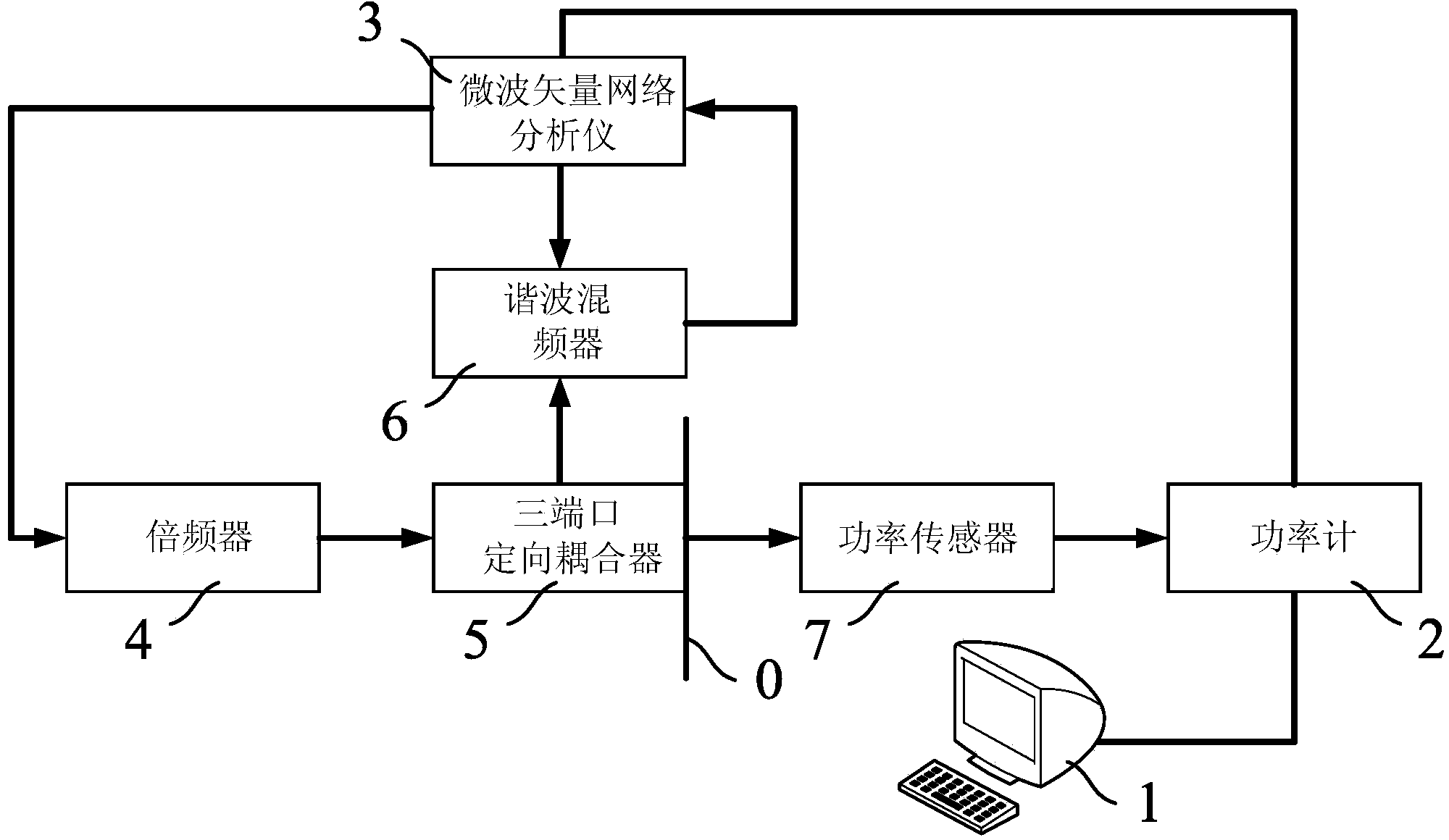
[0067] The power calibration test system of the present invention can work in any frequency band, and only need to select the corresponding frequency band for each module. In this embodiment, the working frequency band is set to the millimeter wave frequency band, that is, the frequency band is set to 30GHZ-300GHZ . Therefore, if Figure 4 As shown, in order to match the working frequency band, the frequency multiplier 4 is a millimeter wave frequency multiplier 41, the three-port directional coupler 5 is a millimeter wave three-port directional coupler 51, and the harmonic mixer 6 is a millimeter wave The harmonic wave mixer 61 and the power sensor 7 are millimeter wave power sensors 71 , and their connection relationship is consistent with that of the power calibration test system described above, which will not be repeated here.

[0068] The working principle of the above millimeter wave power calibration test system is as follows:

[0069] First, in the system setting de...

Embodiment 2

[0072] The present invention provides a power calibration measurement method, the power calibration measurement method at least includes:

[0073] First, build the power calibration test system described above, and use the real-time closed-loop calibration test program set in the system setting device 1 to set the target power and target frequency band.

[0074] In this embodiment, the working frequency band is set as the W band, and the frequency of the W band is 75GHZ~110GHZ. The connection relationship of the hardware part of the W band power calibration test system is basically the same as that of the above power calibration test system. The frequency converter 4 is selected as the W-band sixth frequency multiplier 42, the three-port directional coupler 5 is selected as the W-band three-port directional coupler 52, and the harmonic mixer 6 is selected as the W-band eighth harmonic mixer 62, The power sensor 7 is selected as a W-band power sensor 72 .

[0075] Then, detect...


PUM


Abstract

The invention provides a power calibration test system. The power calibration test system comprises a system setting device for setting target power and a target frequency band, a power meter connected with the system setting device and used for measuring output power in cooperation with a power sensor, a microwave vector network analyzer connected with the power meter and used for generating microwave signals, a frequency multiplier connected with the microwave vector network analyzer, a three-port directional coupler connected with the frequency multiplier, and a harmonic mixer connected with the microwave vector network analyzer and the three-port directional coupler. By means of a closed loop feedback loop, real-time closed loop monitoring and adjustment on input power of the reference plane of an input port of a component to be tested are achieved, real-time closed loop calibration on power within any frequency band and accurate measurement on circuits and devices can be achieved, and the universality, effectiveness, consistency and accuracy of the power calibration test system are largely improved.

Description

technical field [0001] The invention relates to the field of measurement technology, in particular to a power calibration test system and a calibration measurement method. Background technique [0002] Millimeter waves refer to electromagnetic waves with a wavelength of 1-10mm and a frequency of 30GHZ-300GHZ. It is located in the wavelength range where microwaves and far-infrared waves overlap, so it has the characteristics of both spectrums. Millimeter waves are of great significance in communication, radar, guidance, remote sensing technology, radio astronomy, clinical medicine and spectroscopy. The short wavelength and large bandwidth of the millimeter wave make it especially suitable for systems such as missiles, radars, and satellites. Shorter wavelengths result in narrow beamwidths, which provide higher resolution and accuracy for target tracking and identification. When a long-range missile or spacecraft re-enters the atmosphere, it is necessary to use millimeter wa...

Claims


Application Information

Patent Timeline
IPC IPC(8): G01R35/00
Inventor 吴亮孙朋飞丁金义孙晓玮佟瑞孙芸钱蓉李昭音
Owner SHANGHAI INST OF MICROSYSTEM & INFORMATION TECH CHINESE ACAD OF SCI
Why Eureka
Try Eureka