Clock frequency monitor

a clock frequency and monitor technology, applied in the field of clock signals, can solve the problems of ineffective or erroneous synchronization, unstable frequency of ancillary clocks, and inability to always be stabl

Active Publication Date: 2007-07-10
NAT SEMICON CORP
View PDF11 Cites 36 Cited by
  • Summary
  • Abstract
  • Description
  • Claims
  • Application Information

AI Technical Summary

Problems solved by technology

Due to various causes, the frequency of an ancillary clock may not always be stable, even if the clock is generated in synchrony with the reference clock.
If the tendency to drift becomes strong enough, the situation may become unstable and the synchronization may become ineffective or erroneous.
The circuit does not, however, detect the frequency of the clock signal, nor any deviations of the frequency from a given value.
The circuitry of the Smith patent includes an inherently analog circuit and is thus not very suitable for realization on a digital integrated circuit (IC) chip.
Moreover, the circuitry of the Smith patent is relatively complex and thus may not be economical.

Method used


Image

  • Clock frequency monitor
  • Clock frequency monitor
  • Clock frequency monitor

Examples


Embodiment Construction

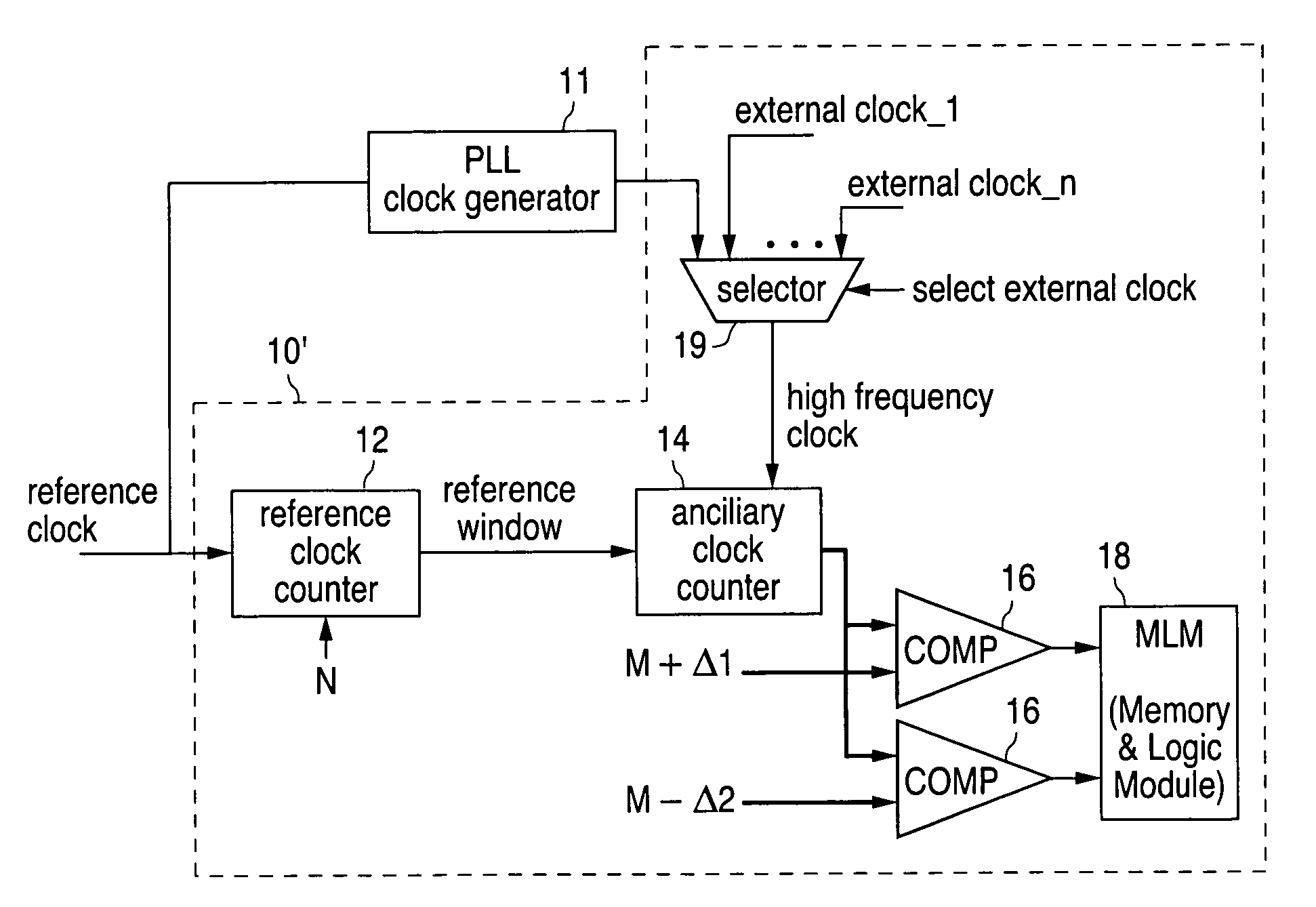
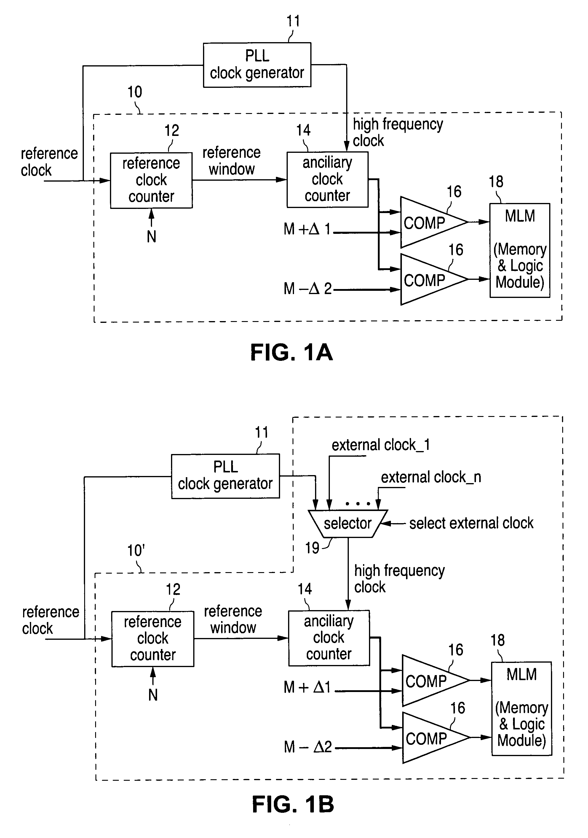
[0027]FIG. 1A illustrates a block diagram that represents an advantageous embodiment of a clock frequency monitor (CFM) 10 in accordance with the principles of the invention. This embodiment is configured to monitor the frequency of a high frequency clock generator 11 that is phase locked to a reference clock by means of a Phase Locked Loop (PLL) that is well known in the art. For convenience clock generator 11 will simply be referred to as PLL 11. Preferably both CFM 10 and PLL 11 are integrated circuits (ICs). More preferably, CFM 10 is built into the same integrated circuit (IC) chip as PLL 11.

[0028]CFM 10 is seen to basically consist of a reference clock counter (RCC) 12, an ancillary clock counter (ACC) 14, two comparators 16 and a Memory & Logic Module (MLM) 18, all interconnected as shown in FIG. 1A. RCC 12 receives a reference clock that is provided within the chip. This clock may be the same reference clock that is fed to PLL 11 or it may be a different one. The RCC also re...


PUM


Abstract

A frequency monitor circuit (FMC) that is part of an integrated circuit chip for monitoring the frequency of one or more clocks present on the chip is disclosed. The FMC includes a reference window generator, operative to output a reference window signal of a given duration, and a clock counter, operative to count all pulses, in any one of the clocks, that occur within the duration of the reference window and to output a corresponding pulse count. The FMC further includes two or more comparators, each operative to compare the pulse count with a respective given threshold value and to output a corresponding indication of frequency deviation. In one configuration, in which the clock is generated on the chip by a frequency multiplier, the reference window generator and the clock counter are shared between the frequency monitor circuit and the frequency multiplier.

Description

CROSS-REFERENCE TO RELATED APPLICATIONS[0001]This patent application claims priority to U.S. Provisional Patent Application Ser. No. 60 / 453,395 filed on Mar. 10, 2003 entitled “CLOCK FREQUENCY MONITOR.”FIELD OF THE INVENTION[0002]This invention relates to clock signals in digital systems and, in particular, to a semiconductor circuit for monitoring the frequencies of such clock signals.BACKGROUND OF THE INVENTION[0003]Digital systems and modules are ubiquitous, serving for a variety of purposes, including data processing, communication and control. In the context of the present specification, a digital system or module may be any of a wide range of sizes and packages, from a single semiconductor chip, through a multiple chip board or module to an assembly of boards or modules. Any of these may form a part of a more general system, such as an electronic system, an electrical power system, an appliance, a vehicle, etc.[0004]Typically a clock signal is provided within the digital syste...

Claims


Application Information

Patent Timeline
Patent Type & Authority Patents(United States)
IPC IPC(8): H03K9/06
CPCG04D7/1207
Inventor ALON, MOSHE
Owner NAT SEMICON CORP
Why Eureka
Try Eureka