Planar laser induced fluorescence (PLIF) imaging device and method for acquiring hydroxyl (OH) concentration spatial distribution through device

A planar laser induction and fluorescence imaging technology, which is applied in the direction of fluorescence/phosphorescence, material excitation analysis, etc., can solve the problems of uncertain concentration spatial distribution, etc., and achieve the effect of improved accuracy and simple process

Inactive Publication Date: 2013-10-09
HARBIN INST OF TECH
View PDF3 Cites 33 Cited by
  • Summary
  • Abstract
  • Description
  • Claims
  • Application Information

AI Technical Summary

Problems solved by technology

[0003] In order to solve the problem that the PLIF imaging technology can only determine the average concentration of the components on a certain line, but cannot determine the spatial distribution of the concentration, the present invention provides a planar laser-induced fluorescence imaging device and using the device to obtain OH method for the spatial distribution of concentrations

Method used


Image

  • Planar laser induced fluorescence (PLIF) imaging device and method for acquiring hydroxyl (OH) concentration spatial distribution through device
  • Planar laser induced fluorescence (PLIF) imaging device and method for acquiring hydroxyl (OH) concentration spatial distribution through device
  • Planar laser induced fluorescence (PLIF) imaging device and method for acquiring hydroxyl (OH) concentration spatial distribution through device

Examples


specific Embodiment approach 1

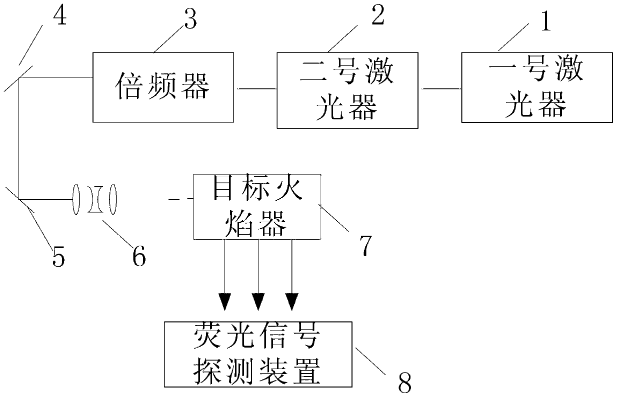
[0026] Specific implementation mode one, combination figure 1 To explain this embodiment, the planar laser-induced fluorescence imaging device described in this embodiment includes the first laser 1, the second laser 2, the frequency doubler 3, the first flat mirror 4, and the second flat mirror 5 , Sheet light shaping system 6, target flame device 7 and fluorescence signal detection device 8. The light beam emitted by the first laser 1 is incident on the optical signal input end of the second laser 2, and the beam pumped by the second laser 2 is input to the multiplier The laser signal input end of the frequency converter 3 is amplified by the frequency multiplier 3 and reflected by the No. 1 flat mirror 4 to the No. 2 flat mirror 5, and the reflected beam reflected by the No. 2 flat mirror 5 is incident on the sheet The light shaping system 6, the sheet light beam obtained after shaping by the sheet light shaping system 6 is input to the target flamer 7;

[0027] The fluorescen...

specific Embodiment approach 2

[0028] Embodiment 2 This embodiment is a further description of the planar laser-induced fluorescence imaging device described in Embodiment 1. The sheet light shaping system 6 uses CH 4 / O 2 / N 2 Laminar flow premixed Bunsen flame lamp, and the stoichiometric ratio Φ=1.0.

specific Embodiment approach 3

[0029] Specific embodiment 3. The embodiment is a further description of the planar laser-induced fluorescence imaging device described in specific embodiment 1, and the first laser 1 adopts an Nd:YAG laser.


PUM

PropertyMeasurementUnit
wavelengthaaaaaaaaaa

Abstract

The invention discloses a planar laser induced fluorescence (PLIF) imaging device and a method for acquiring hydroxyl (OH) concentration spatial distribution through the device, and relates to a method for determining the OH-radical concentration spatial distribution. According to the device and the method, the problem that the average concentration of components on a certain line can be only determined and the spatial distribution of the concentration cannot be determined through a PLIF imaging technology is solved. A laser generates a laser signal, the laser signal is subjected to frequency multiplication through a frequency multiplier, and a sheet pulse signal is obtained through a sheet beam reshaping system; a target flame device excites an OH-radical fluorescence signal; a fluorescence signal detection device detects the OH-radical fluorescence signal to obtain an OH-radical fluorescence image; n to-be-measured points and n auxiliary points are selected from the OH-radical fluorescence image, the gray value and light intensity of the OH-radical fluorescence image of each to-be-measured point and each auxiliary point are calculated; the average molar concentration of each to-be-measured point is obtained according to a Lambert-Bill absorption law so as to obtain the OH-radical concentration spatial distribution. The invention is applied to the method for determining the OH-radical concentration spatial distribution.

Description

Technical field [0001] The invention relates to a method for determining the spatial distribution of OH group concentration. Background technique [0002] In recent years, with the rapid development of aerospace technology and the emphasis on energy conservation and emission reduction, the study of combustion mechanism and combustion technology has attracted more and more attention, and the study of the concentration of each component in the combustion process is one of the important aspect. Planar laser induced fluorescence (PLIF) imaging technology is currently a highly sensitive technology widely used in combustion diagnosis. However, obtaining concentration information through PLIF imaging technology needs to determine many parameters, and these parameters are also being studied at this stage, so there is great uncertainty. In addition, the use of PLIF imaging technology can only determine the components on a certain line It is difficult to determine the spatial distributio...

Claims


Application Information

Patent Timeline
Patent Type & Authority Applications(China)
IPC IPC(8): G01N21/64
Inventor 于欣彭江波杨振李晓晖樊荣伟陆威陈德应李旭东董志伟张亚丽贾博阳
Owner HARBIN INST OF TECH
Why Eureka
Try Eureka