Method and apparatus for multipath mitigation using antenna array

a multi-path mitigation and antenna array technology, applied in antennas, electrical equipment, radio transmission, etc., can solve problems such as ambiguity resolution, difference in phase delay of carrier signal received by base and rover receivers may substantially exceed one cycle, and it is not possible to measure the integer number of cycles from the incoming satellite signal

Active Publication Date: 2005-04-19
TOPCON GPS
View PDF10 Cites 29 Cited by
  • Summary
  • Abstract
  • Description
  • Claims
  • Application Information

AI Technical Summary

Problems solved by technology

The practical implementation of those advantages, which might otherwise be guaranteed by the measurement of the carrier phases, runs into the problem of ambiguity resolution for phase measurements.
Therefore, the difference in the phase delays of a carrier signal received by the Base and Rover receivers may substantially exceed one cycle.
Second, it is not possible to measure the integer number of cycles from the incoming satellite signals; one can only measure the fractional part.
One of the problems with satellite navigation receivers is that satellite signals are difficult to detect in certain circumstances.
Various environmental influences and interference signals cause measurement errors.
One of the major sources of error in satellite navigation receivers is multipath error.
Multipath error is caused by satellite signals reflecting off various surfaces (e.g., buildings).
If these multipath signals are tracked in the satellite receiver, positioning errors will occur.
One problem with multipath mitigation using this technique is energy loss (i.e., reduction in signal-to-noise ratio) and the inability to suppress multipath errors caused by reflected signals with delay less than 10 . . . 30 m with respect to the direct signal.
While phased antenna arrays may be useful in reducing multipath signals, one problem with phased antenna arrays is the computational complexity required in the receiver.
Such receivers generally require a powerful processor to process the signals from the multiple antenna elements, have high power consumption, and have relatively large physical dimensions.

Method used


Image

  • Method and apparatus for multipath mitigation using antenna array
  • Method and apparatus for multipath mitigation using antenna array
  • Method and apparatus for multipath mitigation using antenna array

Examples


Embodiment Construction

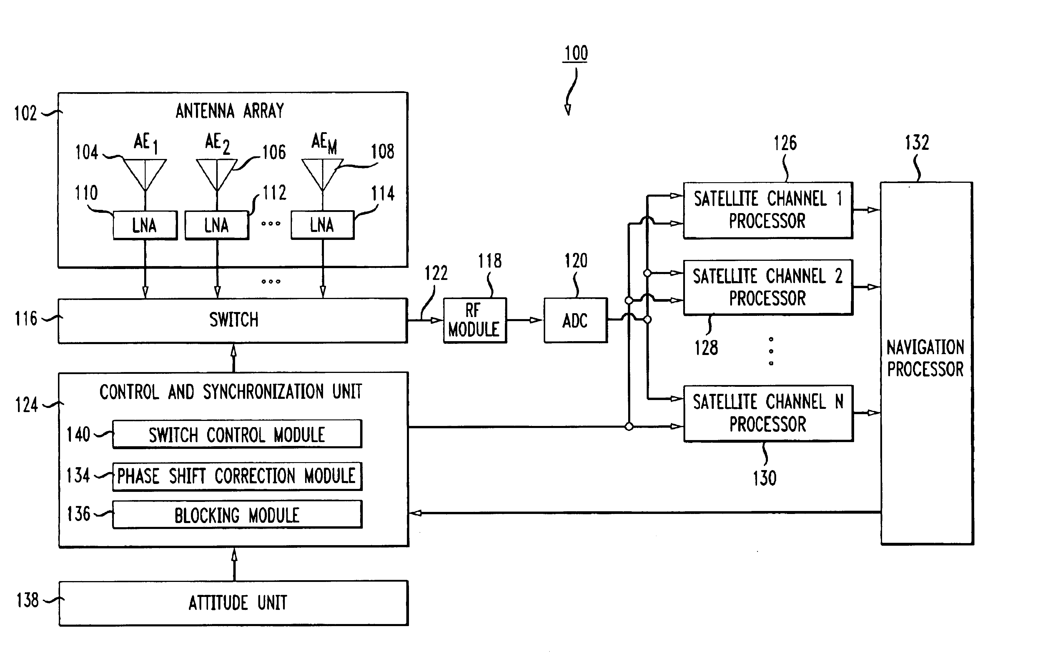
[0025]The principles of the present invention may be implemented in connection with various types of satellite navigation receivers. For example, in a differential navigation system, the principles of the present invention may be applied to a Rover satellite receivers or a Base satellite receiver.

[0026]FIG. 1 shows a high level block diagram of a satellite receiver 100 in accordance with one embodiment of the invention. It is noted that the block diagrams used herein are meant to describe the high level functioning and configuration of a unit. One skilled in the art would readily recognize that some of the blocks represent hardware components while other blocks represent some function or operation. The functions and operations may be performed by hardware circuits, software instructions executing on a processor, firmware, or some combination of hardware and software. Given the description herein, those skilled in the art would be able to implement the described functionality using w...


PUM


Abstract

Disclosed is a method and apparatus for multipath mitigation using an antenna array. An antenna array made up of a plurality of antennas is used to receive satellite signals from satellites. Various configurations of antenna arrays is disclosed, including a linear vertical antenna array and a horizontal antenna array in which the antenna elements are located in a horizontal plane. A switch sequentially connects each of the antenna outputs to a single processing path to generate a common additive signal. The common additive signal is provided to satellite channel processors, each of which processes the signals from an associated satellite. A phase shift correction signal associated with each of the antennas is generated and synchronously applied to a carrier phase reference signal. A blocking signal may be applied to the satellite channel processors in order to block the processing of signals from an unwanted satellite.

Description

BACKGROUND OF THE INVENTION[0001]This invention relates generally to satellite navigation receivers and more particularly to multipath mitigation in a satellite navigation receiver.[0002]Satellite navigation systems, such as GPS (USA) and GLONASS (Russia), are well known in the art and are intended for highly accurate self-positioning of users possessing special navigation receivers. A navigation receiver receives and processes radio signals transmitted by satellites located within line-of-sight distance of the receivers. The satellite signals comprise carrier signals that are modulated by pseudo-random binary codes. The receiver measures the time delay of the received signal relative to a local reference clock or oscillator. These measurements enable the receiver to determine the so-called pseudo-ranges between the receiver and the satellites. The pseudo-ranges are different from the ranges (distances) between the receiver and the satellites due to various noise sources and variati...

Claims


Application Information

Patent Timeline
Patent Type & Authority Patents(United States)
IPC IPC(8): H01Q3/30
CPCH01Q3/30
Inventor VOROBIEV, MICHAEL YU.ZHODZISHSKY, MARK I.VEITSEL, ANDREW V.VEITSEL, VICTOR A.ZHDANOV, ALEXEY V.PUSHKAREV, SERGEY N.
Owner TOPCON GPS
Why Eureka
Try Eureka