Universal jamb bracket for a door closing system

a technology for door closing systems and jamb brackets, applied in hinges, wing accessories, manufacturing tools, etc., can solve the problems of reducing the effectiveness of door closers, affecting the safety of doors, and affecting the appearance of door closing jamb brackets, so as to achieve greater strength, reduce the thickness of metal at the barriers, and improve the stability.

Inactive Publication Date: 2005-04-26
LIBES BARRY
View PDF4 Cites 5 Cited by
  • Summary
  • Abstract
  • Description
  • Claims
  • Application Information

AI Technical Summary

Benefits of technology

[0014]The basal element provides two securing segments. These segments extend perpendicularly from the basal element in order to hug the edge or corner of the doorjamb. This provides for greater stability and greater strength for the entire door closing system. The securing segments are attached through screw holes. These screw holes are countersunk so that the screw heads do not interfere with the action of the door.
[0015]The basal element also provides snap-off grooves. The snap-off grooves extend across the width of the basal element. The thickness of the metal at the barriers is significantly decreased from that of the remainder of the basal element. When the basal element is bent to a specific angle at the snap-off groove, an end of the basal element may be broken off. This gives t...

Problems solved by technology

Conventional door closing jamb brackets are problematic when a strong door opening force jerks and loosens the fasteners connecting the jamb bracket to the doorjamb.
Both remedies frequently further tear out the doorjamb, damaging its appearance and reducing the effectiveness of the door closer.
However, if the jamb bracket is relocated inward toward the center of the doorjamb, maximum door swing is compromised.
If the jamb bracket is relocated either above or below the worn holes, the result is a horizontal tilting of the door closing system.
Another more complicated yet permanent solution involves the complete relocation of the entire door cl...

Method used


Image

  • Universal jamb bracket for a door closing system
  • Universal jamb bracket for a door closing system
  • Universal jamb bracket for a door closing system

Examples


Embodiment Construction

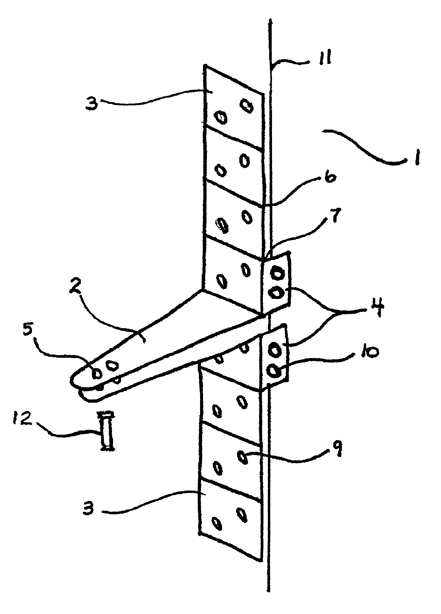
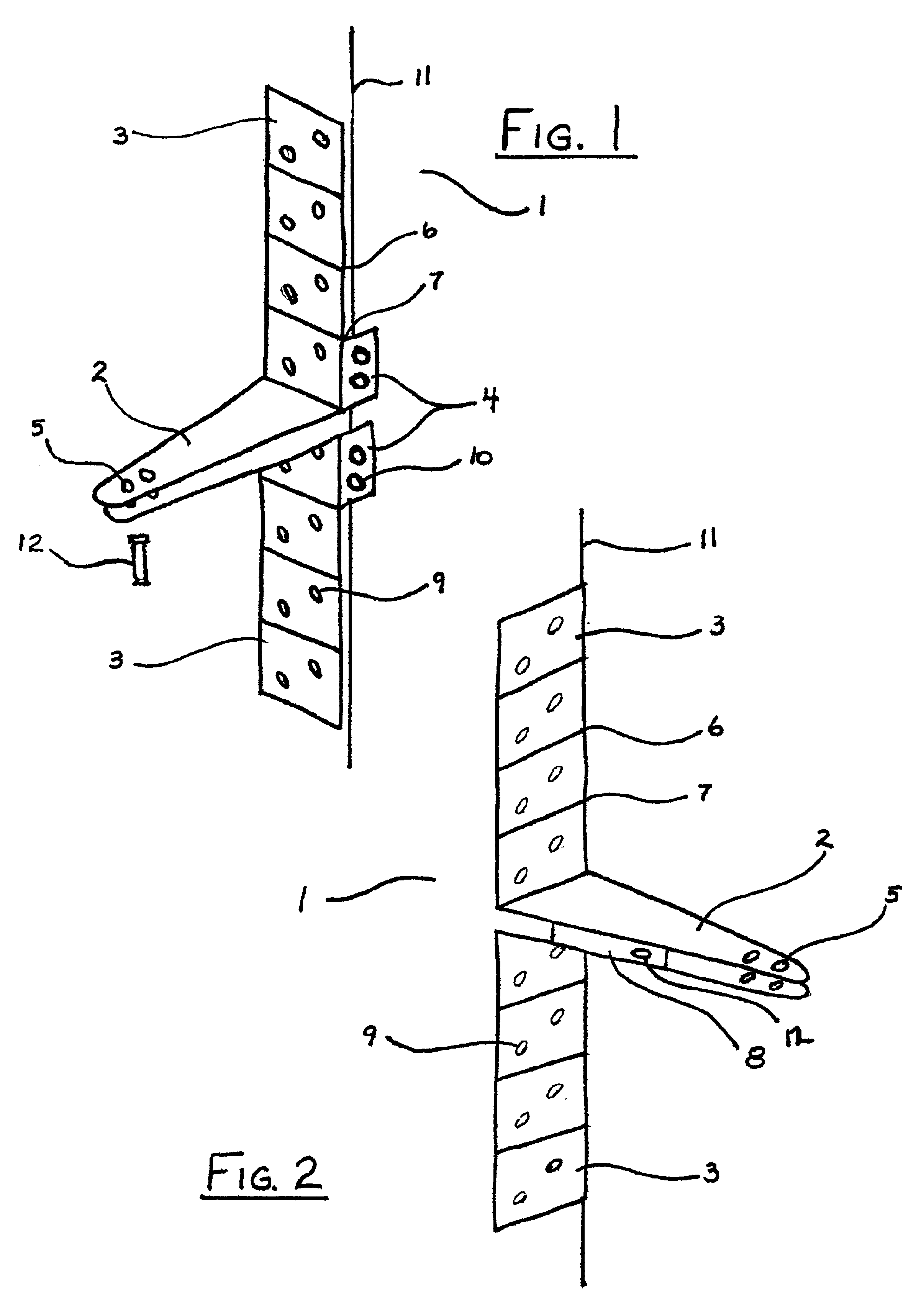
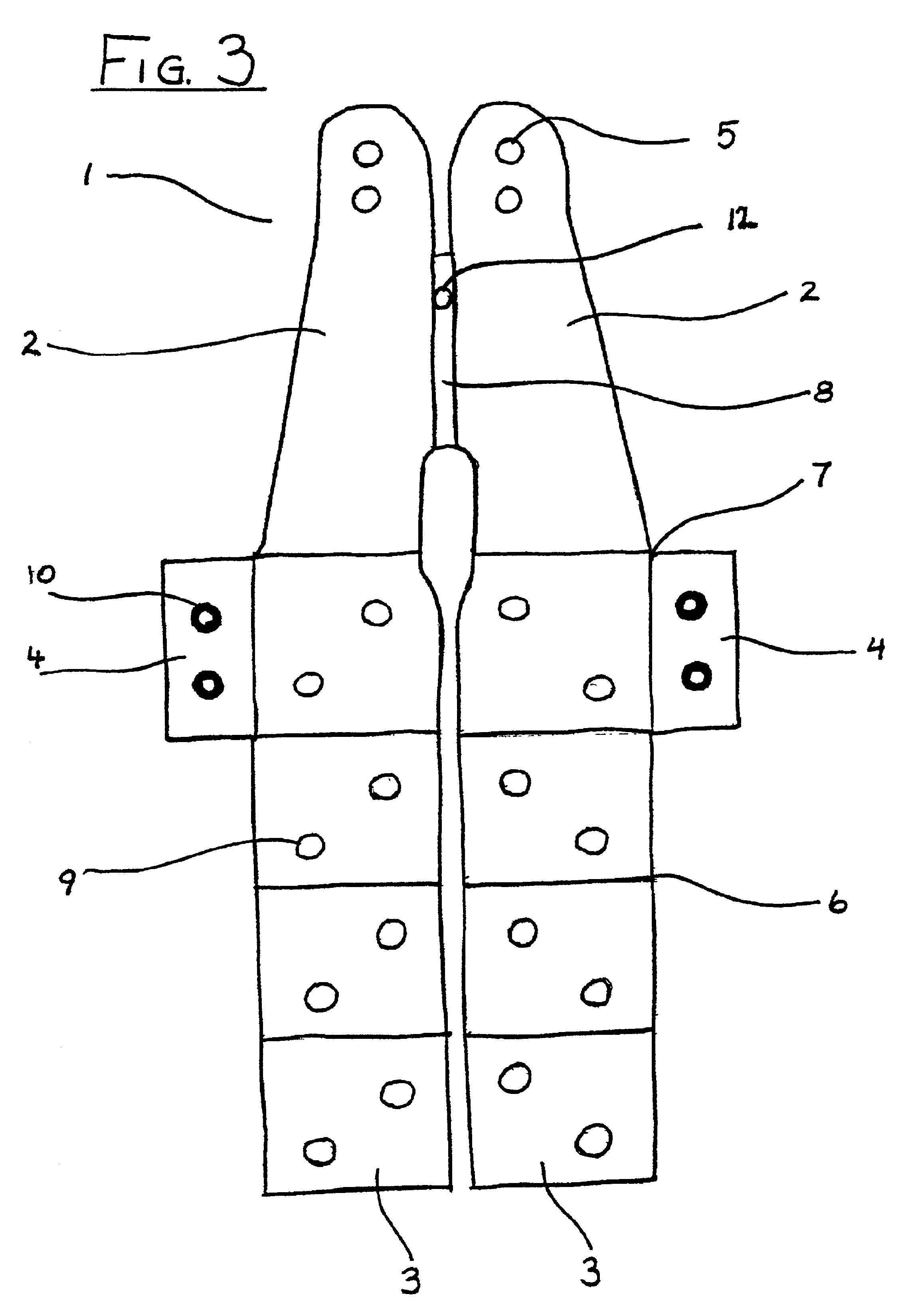
[0027]FIG. 1 is a perspective view of the jamb bracket 1 used as part of a door closing system. Specifically, jamb bracket 1 secures the door closing system to doorjamb 11. Arm structure 2 extends outward from the center of the jamb bracket to meet the other elements of the door closing system. Arm structure 2 is 1-1 ¼″ wide and has a top and bottom portion. The width of arm structure 2 is decreased from that of the normal jamb bracket to allow for weather-stripping of varying thickness. Four pivot holes 5 are disposed at the end of the arm structure 2, two in each portion. The respective holes are aligned vertically and those on the same portion of arm structure 2 are separated from each other by ⅜″. Pivot fastener pin 12 of the door closing system is used to attach a piston rod to jamb bracket 1.

[0028]Basal element 3 extends perpendicularly above and below arm structure 2. Basal element 3 has a top and bottom portion. Basal element 3 lies flush against doorjamb 11 and is secured t...


PUM


Abstract

A jamb bracket for a door closing system having an arm structure ending out from a basal element with two securing segments hugging an edge or corner of a doorjamb. The basal element has snap-off grooves with a decreased thickness allowing the portion of the basal element beyond the snap-off groove to be broken off if not needed. Two additional snap-off grooves separate the basal element from the securing segments so that the securing segments may be removed if necessary. The arm structure has two receiving areas for the pin of the door closing system. The jamb bracket is adaptable to become either a corner bracket for a corner/ceiling door closing system or an in-swinging bracket for an in-swinging door closing system.

Description

BACKGROUND OF THE INVENTION[0001]1. Field of the Invention[0002]The invention relates to door closing systems and more particularly to the jamb bracket of the system. The jamb bracket is mounted on a doorjamb and attaches the door closing system to the doorjamb. Door closing systems are conventionally mounted between a storm door and a wooden doorjamb to control the opening and closing of the door.[0003]2. Prior Art[0004]A door closing system normally comprises a piston assembly that includes a jamb bracket or stability control bracket. The jamb bracket is usually manufactured from a single piece of steel, which is stamped into a distinct and functional configuration. The jamb bracket distances the pivot connection for the door closing system from the doorjamb structure. It also provides a remote hinging area for securing the piston rod of the door closing system.[0005]There are two main structures that normally comprise the jamb bracket; an arm structure and a basal structure. The ...

Claims


Application Information

Patent Timeline
IPC IPC(8): E05F3/00E05F3/22E05D5/06E05F3/10E05D5/00
CPCE05F3/22E05D5/06E05F3/108Y10T16/95E05Y2900/132Y10T16/56Y10S16/43
Inventor LIBES, BARRY
Owner LIBES BARRY
Why Eureka
Try Eureka