Plant for removing fines from fiber fluff

a technology for fines and fiber fluff, which is applied in the field of fines removal plants for fiber fluff, can solve the problems of reducing the quality of air-laid webs, complex filters having a number of filtering steps, and expensive stop-down of the total plant, and achieves the effect of separating in a simple fine from paper flu

Inactive Publication Date: 2005-04-26
OERLIKON TEXTILE GMBH & CO KG
View PDF10 Cites 0 Cited by
  • Summary
  • Abstract
  • Description
  • Claims
  • Application Information

AI Technical Summary

Benefits of technology

[0021]The present invention now provides a plant for effectively separating in a simple fines from paper fluff.

Problems solved by technology

These fines tend to reduce the quality of the air-laid web and with that also the products which are manufactured of the web.
The dispersed fines in the reused water tend to get stuck in the fine nozzles which then stop to function thereby causing a costly stop-down for the total plant.
Filtering particles as small as fines require, however, a complex filter having a number of filtering steps.
The filter in itself and the servicing of the filter are therefore very costly.

Method used


Image

  • Plant for removing fines from fiber fluff
  • Plant for removing fines from fiber fluff

Examples


Embodiment Construction

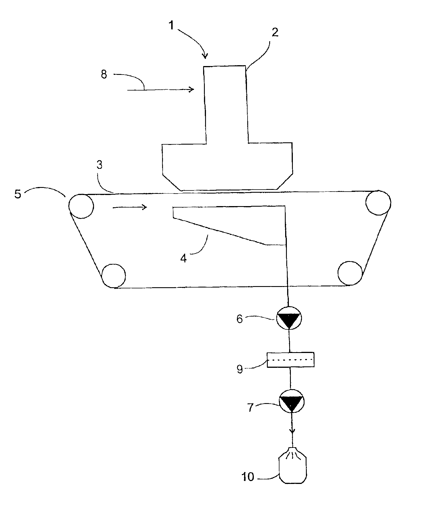
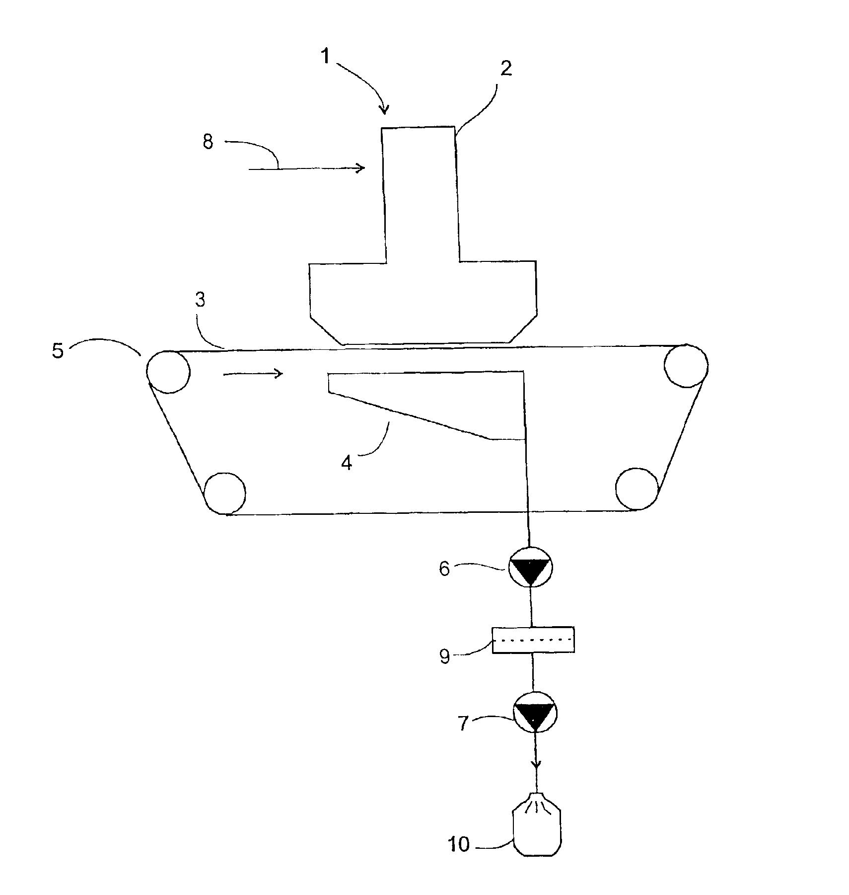
[0026]FIG. 1 shows a forming station 1 which mainly consists of a forming head 2 placed above a forming wire 3 and a suction box 4 placed below the forming wire. The forming wire runs, during operation, around four rolls 5 in the direction indicated by the arrow. A differential pressure is generated over the forming wire by means of first and second vacuum fans 6, 7 which are connected to the suction box 4.

[0027]Fibers from a supply of fibers (not shown) are via a channel 8 carried into the forming head in a flow of air. The fibers are by means of the differential pressure deposited in a layer of fluff onto the forming wire.

[0028]The fluff normally contains fines, which are small fiber particles on the order of 10 to 50μ. For removing the fines from the fluff the mesh count of the forming wire and the differential pressure between the forming head and the suction box are chosen such that mainly only fines contained in the fluff are allowed to pass the forming wire.

[0029]The mesh cou...


PUM

PropertyMeasurementUnit
pressureaaaaaaaaaa
differential pressureaaaaaaaaaa
weightsaaaaaaaaaa

Abstract

A plant for removing fines from fiber fluff. The plant includes a forming wire, a forming head which is placed above the forming wire and arranged for air-laying fiber fluff into a layer upon the forming wire, at least one channel for carrying, in a flow of air, fibers from a supply of fibers into the forming head, a suction box placed beneath the forming wire, at least one vacuum fan connected to the suction box for generating an air flow from the forming head, through the fluff, the forming wire, and the suction box to the at least one vacuum fan. The mesh count of the forming wire mainly allow only the fines contained in the fluff to pass through the forming wire. The troublesome and costly filtering of the water used in a hydroentangling process is advantageously eliminated when using fluff, which is freed from fines by means of the plant according to the invention. Air-laid webs produced of the fine-free fibers also have a high quality.

Description

CROSS-REFERENCE TO RELATED APPLICATION[0001]This application is a continuation of International Application PCT / DK00 / 00711 filed Dec. 19, 2000, the entire content of whichis expressly incorporated herein by reference thereto.BACKGROUND ART[0002]The invention relates to a plant for removing fines from fiber fluff comprising a forming wire, a forming head which is placed above the forming wire and arranged for air-laying fiber fluff into a layer upon the forming wire, at least one channel for carrying, in a flow of air, fibers from a supply of fibers into the forming head, a suction box placed at the lower side of the forming wire, at least one vacuum fan connected to the suction box for generating an air flow from the forming head, through the fluff, the forming wire, and the suction box to the at least one vacuum fan.[0003]Fluff of e.g. cellulose fibers and / or synthetic fibers is generally used for producing air-laid webs in plants where the fluff is air-laid in layers upon at least...

Claims


Application Information

Patent Timeline
Patent Type & Authority Patents(United States)
IPC IPC(8): D04H1/70D04H1/72D04H1/425D04H1/732
CPCD04H1/425D04H1/732D04H1/72
Inventor ANDERSEN, JENS OLE BROCHNER
Owner OERLIKON TEXTILE GMBH & CO KG
Why Eureka
Try Eureka