Downdraft nebulizer

a nebulizer and downdraft technology, applied in the field of pneumatic nebulizers, can solve the problems of limited function and inconvenient structure of devices of this typ

Inactive Publication Date: 2005-04-26
BABYS BREATH LTD
View PDF23 Cites 38 Cited by
  • Summary
  • Abstract
  • Description
  • Claims
  • Application Information

AI Technical Summary

Problems solved by technology

It is obvious by their designs that the above mentioned devices are intended for deployment at a designated orientation, and that proper function is limited to a relatively small range of variance from the designated orientation.
In practical use, however, it would sometimes advantageous to deploy a nebulizer at an orientation outside the tolerances of these devices.
Devices of this type are not structurally nor mechanically suited, nor are they intended for delivery for an extended time period of several minutes, nor do they teach nor suggest such application.

Method used


Image

  • Downdraft nebulizer
  • Downdraft nebulizer
  • Downdraft nebulizer

Examples


Embodiment Construction

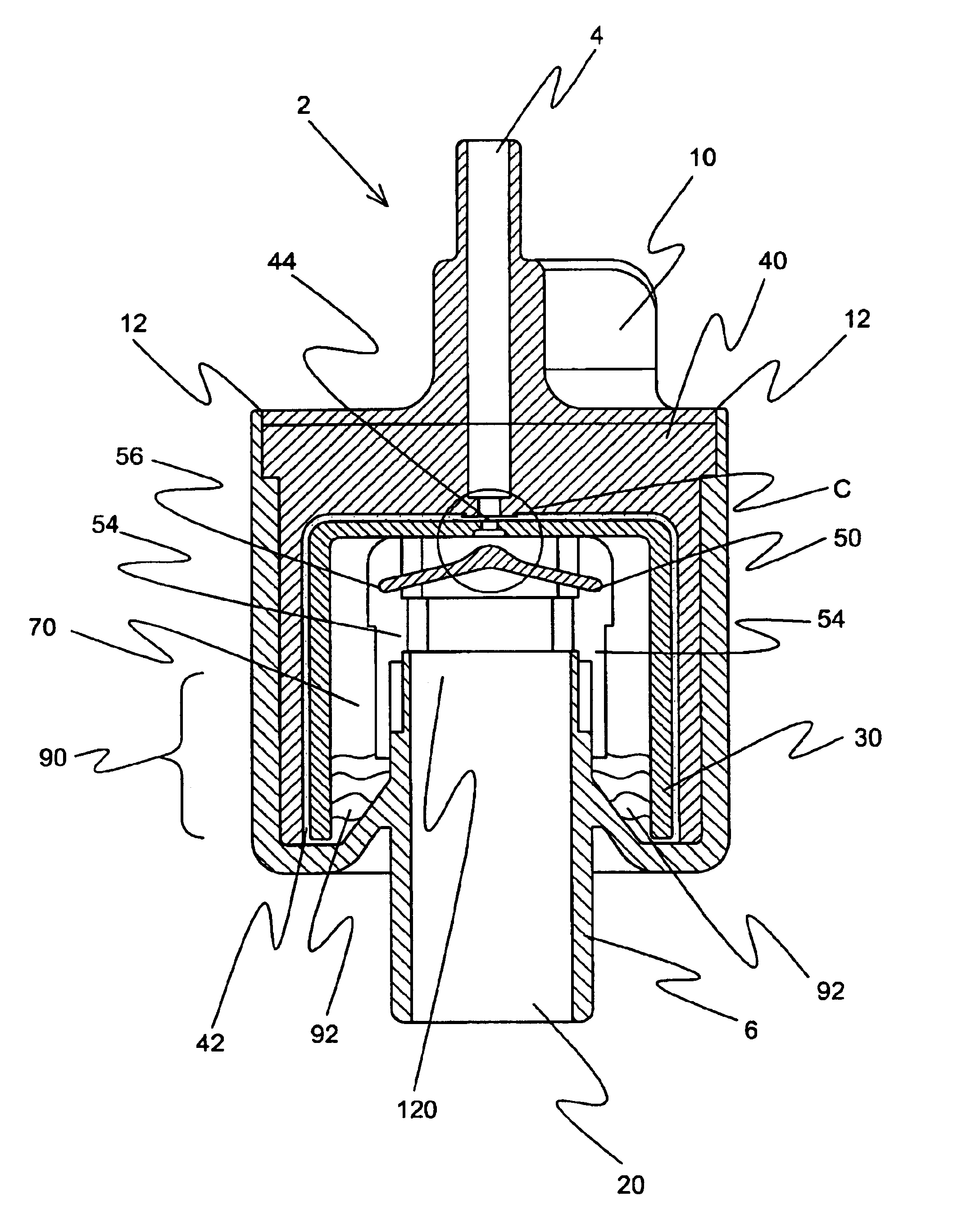
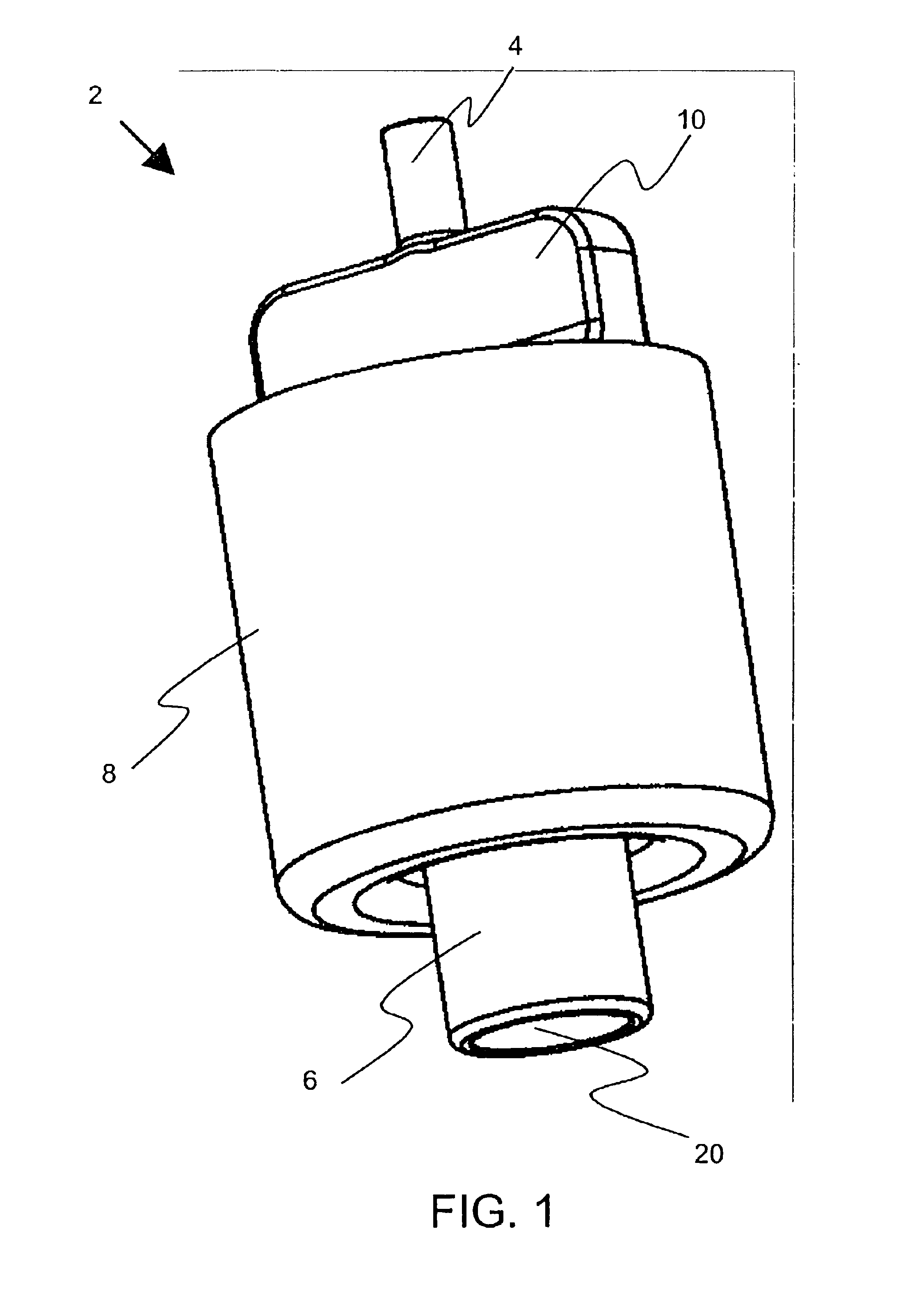
[0068]The present invention a pneumatic nebulizer in which aerosol mist is produced in a downwardly flowing direction, the aerosol mist then leaves the nebulizer through a downwardly projecting aerosol outlet, that is to say, a downdraft nebulizer.

[0069]The principles and operation of downdraft nebulizer according to the present invention may be better understood with reference to the drawings and the accompanying description.

[0070]By way of introduction, the nebulizers presently in general use are configured for discharge of medication mist either into an inhalation interface or directly into the environment. Typically, the intention of nebulizers used for extended time administration is produce a flow of droplets of medication in atmospheric suspension to an inhalation interface, usually a mouth piece. The medicated mist is generally discharged in an upward or sideward direction since this is the easiest way to deal with the problem of trapping drops that are too large to be aspir...


PUM


Abstract

A pneumatic nebulizer for the delivery of medications that produces aerosol mist in a downward direction. A gas inlet introduces a high velocity gas that passes through a venturi orifice producing a venture effect. A liquid stored in a reservoir is drawn into the orifice, atomizing forming droplets. The droplets are further atomized by hitting a baffle. The mist formed substantially circumscribes the baffle.

Description

FIELD AND BACKGROUND OF THE INVENTION[0001]The present invention relates to pneumatic nebulizers and, in particular, it concerns a pneumatic nebulizer in which aerosol mist is produced in a downwardly flowing direction, the aerosol mist then leaves the nebulizer through a downwardly projecting aerosol outlet.[0002]It is known to provide a nebulizer for the production of a high volume of aerosol for inhalent delivery of medications. In general pneumatic nebulizers atomize liquids by introducing small amounts of the liquid into a flow of high velocity air, which serves to break up the liquid into small droplets. Usually, the liquid is as drawn from a reservoir and aspirated into the airflow by means of a venturi effect created by structural elements of the device. The air and liquid mixture then continues in an upward direction to an aerosol outlet. The medicated aerosol mist is then administered to a patient by means of a therapeutic inhalation interface or by discharge of the mist i...

Claims


Application Information

Patent Timeline
Patent Type & Authority Patents(United States)
IPC IPC(8): A61G10/04A61G10/00A61M15/00A61M11/06A61M16/06
CPCA61G10/04A61M11/06A61M16/0627A61M16/06A61M15/0086A61M2209/084
Inventor HALAMISH, ASAF
Owner BABYS BREATH LTD
Why Eureka
Try Eureka