
Overhead bin and monument attachment support system

Active Publication Date: 2005-04-26
THE BOEING CO
View PDF17 Cites 122 Cited by
  • Summary
  • Abstract
  • Description
  • Claims
  • Application Information

AI Technical Summary

Benefits of technology

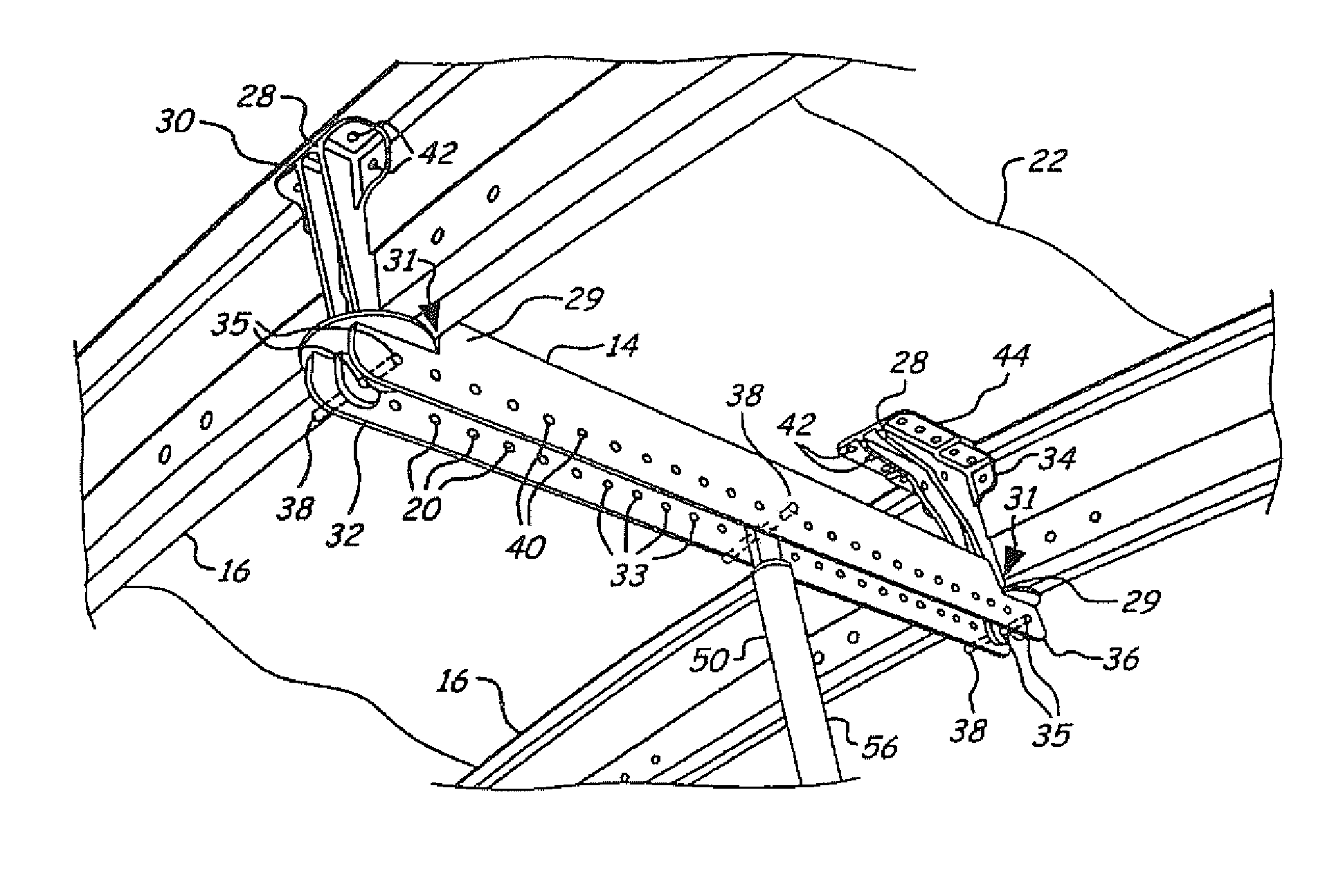
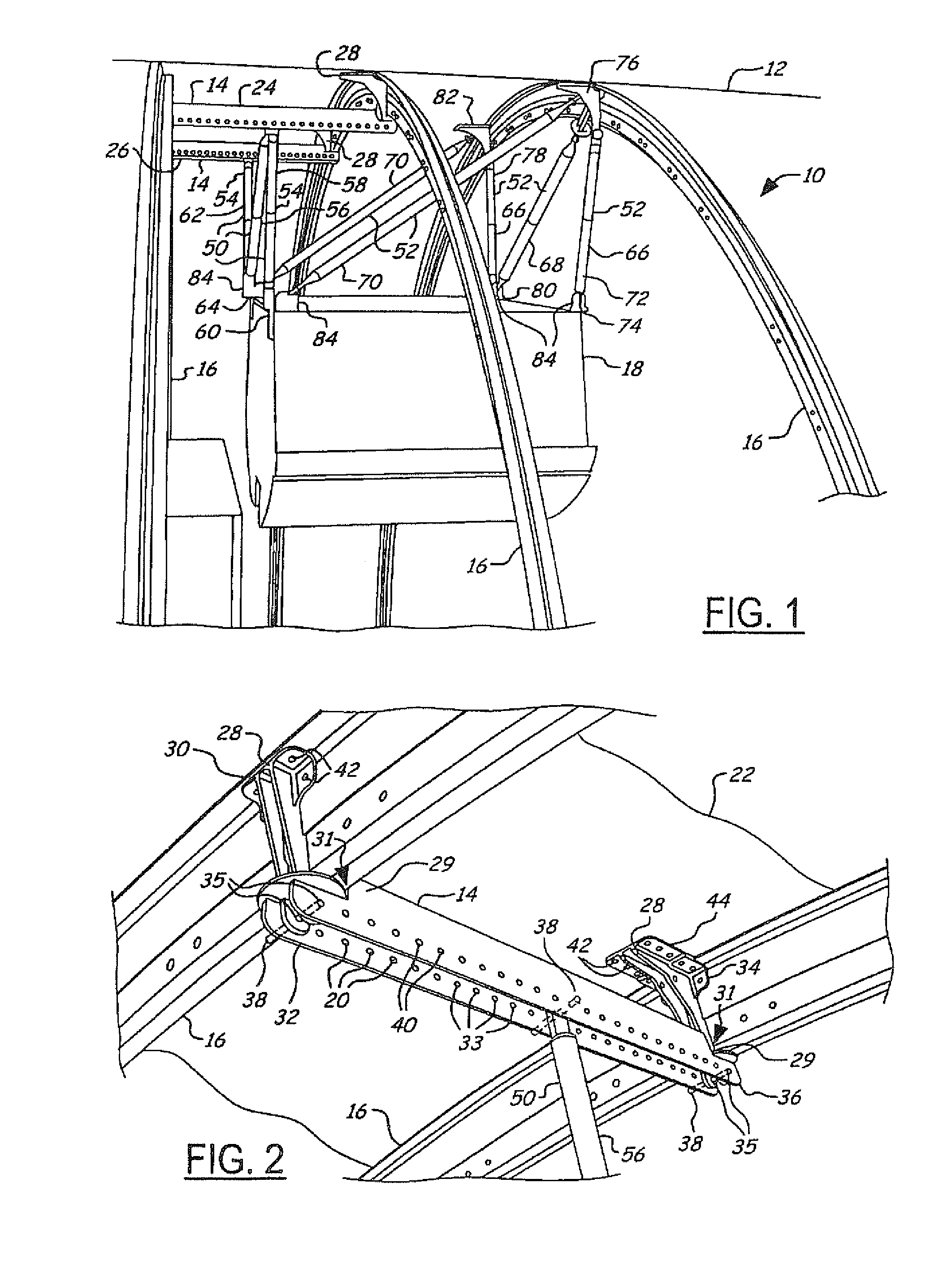
[0009]The embodiments of the present invention provide several advantages. One such advantage is the provision of a bin and monument support system that utilizes adapter bridges instead of rails to support bins and monuments of an aircraft. The use of the adaptor bridges accounts for irregular sized stowage bins and for instances when stowage bins do not align properly with frame elements of an aircraft. The use of adapter bridges also minimizes the amount, size, weight, and cost of materials and components utilized to support the bins and monuments. The adapter bridges allow for various interior feature configurations and support thereof.
[0010]Another advantage provided by an embodiment of the present invention is the provision of a bin and monument support system that in addition to the above stated advantage also provides adequate and appropriate support of bins and monuments during an emergency landing of an aircraft.
[0011]Yet another advantage provided by still another embodiment of the present invention is the provision of a bin and monument support system that accounts for movement between components and structures and for variations in tolerances of bin, monument, and aircraft structures. In so doing, the stated embodiment minimizes the preloading of support system components, bins, and monuments during manufacturing and minimizes the fatigue experienced during the operation of an aircraft, which increases life of the components, bins, and monuments and aids in maintaining integrity thereof.

Problems solved by technology

Support systems for interior features within a twin aisle aircraft, such as the Boeing Company 747 and 777 models, have become increasingly complex, due to the ever-increasing number of interior configurations that airline customers desire.
Although the rail support system provides increased configuration flexibility over that of a simple tie rod support system, it is expensive to manufacture and implement.
Also, due to the additional weight of the rails, fuel consumption and therefore range of an aircraft can be affected.
Although the cross-members provide additional support, they also increase the weight of the support system.

Method used


Image

  • Overhead bin and monument attachment support system
  • Overhead bin and monument attachment support system
  • Overhead bin and monument attachment support system

Examples


Embodiment Construction

[0023]In the following Figures the same reference numerals will be used to refer to the same components. While the present invention is described primarily with respect to overhead bin and monument support systems for an aircraft, the present invention may be adapted and applied in various vehicle and non-vehicle applications. The present invention may be applied in aeronautical applications, nautical applications, railway applications, automotive vehicle applications, and commercial and residential applications, as well as in other applications known in the art where stowage bins and monuments of various size and shape are utilized and supported.

[0024]In the following description, various operating parameters and components are described for one constructed embodiment. These specific parameters and components are included as examples and are not meant to be limiting.

[0025]Referring now to FIGS. 1 and 2, a perspective side view of an overhead bin support system 10 for an aircraft 12...


PUM


Abstract

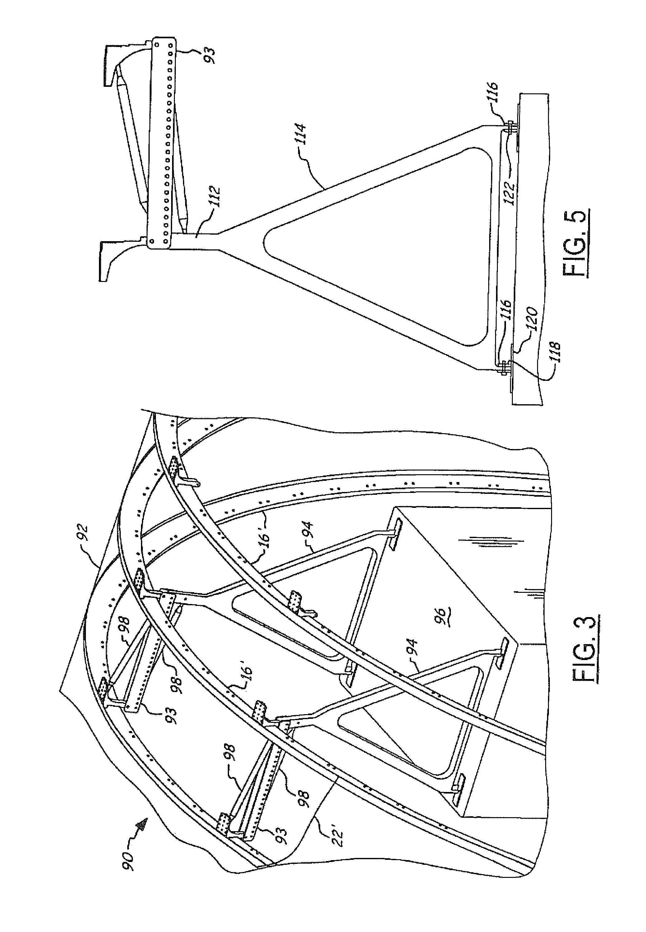
A monument support system (90) for an aircraft (92) includes multiple aircraft frame elements (16″). An adapter bridge (93) is coupled to the aircraft frame elements (16″) and has multiple attachment points (20″). A coupling member (110) is coupled to the adapter bridge (93). A monument (96) is coupled to the frame elements (16″) via the adapter bridge (93) and the coupling member (110).

Description

BACKGROUND OF INVENTION[0001]The present invention is related generally to aircraft stowage bins and monuments. More particularly, the present invention is related to the attachment and support of stowage bins and monuments within an aircraft.[0002]There exists an increasing demand for aircraft interior systems that are capable of supporting various interior features. The interior features include an increasing number of possible seat, bin, ceiling, and monument interior configurations that airline customers desire. A monument, for example, can refer to a stowage bin, a closet, a galley, a lavatory, or the like.[0003]Support systems for interior features within a twin aisle aircraft, such as the Boeing Company 747 and 777 models, have become increasingly complex, due to the ever-increasing number of interior configurations that airline customers desire. The support systems are designed to account for a majority of the desired configurations. The support systems typically include fo...

Claims


Application Information

Patent Timeline
IPC IPC(8): B64C1/00B64C1/06B64D11/00
CPCB64D11/003B64C1/06
Inventor SCOWN, STEPHEN L.
Owner THE BOEING CO
Learn More