Radio-frequency imaging system for medical and other applications

a radio-frequency imaging and other technology, applied in the field of imaging systems, can solve the problems of ionizing radiation systems with dangers and risks associated with their use, stationary and quite expensive to use,

Inactive Publication Date: 2005-04-26
GLEMAN STUART M
View PDF16 Cites 67 Cited by
  • Summary
  • Abstract
  • Description
  • Claims
  • Application Information

AI Technical Summary

Benefits of technology

[0011]The present invention is a lightweight, portable imaging system for medical and other applications in which the internal structures of an overall object must be seen without invading or damaging the object or exposing it to ionizing radiations, or immersing it in a strong magnetic field. This system is particularly useful for viewing the internal organs and structures of living creatures. The instrument works by transmitting electromagnetic waves of single or a multiplicity of frequencies, where these frequencies are referred to as “radio frequencies”, and where “radio frequency” refers to the entire band of frequencies of electromagnetic radiation from extremely low (approaching zero) to optical frequencies, but specifically excluding X-rays and gamma rays, through the object (for example the human body) and measuring the absorption and scattering of these waves by the various structures and inhomogeneities of the object, using scanning sub-wavelength resolution detectors. An “X-Ray” type of image can be created by an x-y planar scan of the detectors (and sometimes the source) over the object. A “CAT-Scan” three-dimensional image can be created by a cylindrical (theta-z) scan of the detectors and sources around and along the object.

Problems solved by technology

All of the ionizing radiation systems have dangers and risks associated with their use, particularly to human subjects.
The MRIs are less invasive but use a large and very expensive superconducting magnet, which makes them stationary and quite expensive to use.

Method used


Image

  • Radio-frequency imaging system for medical and other applications
  • Radio-frequency imaging system for medical and other applications
  • Radio-frequency imaging system for medical and other applications

Examples


Embodiment Construction

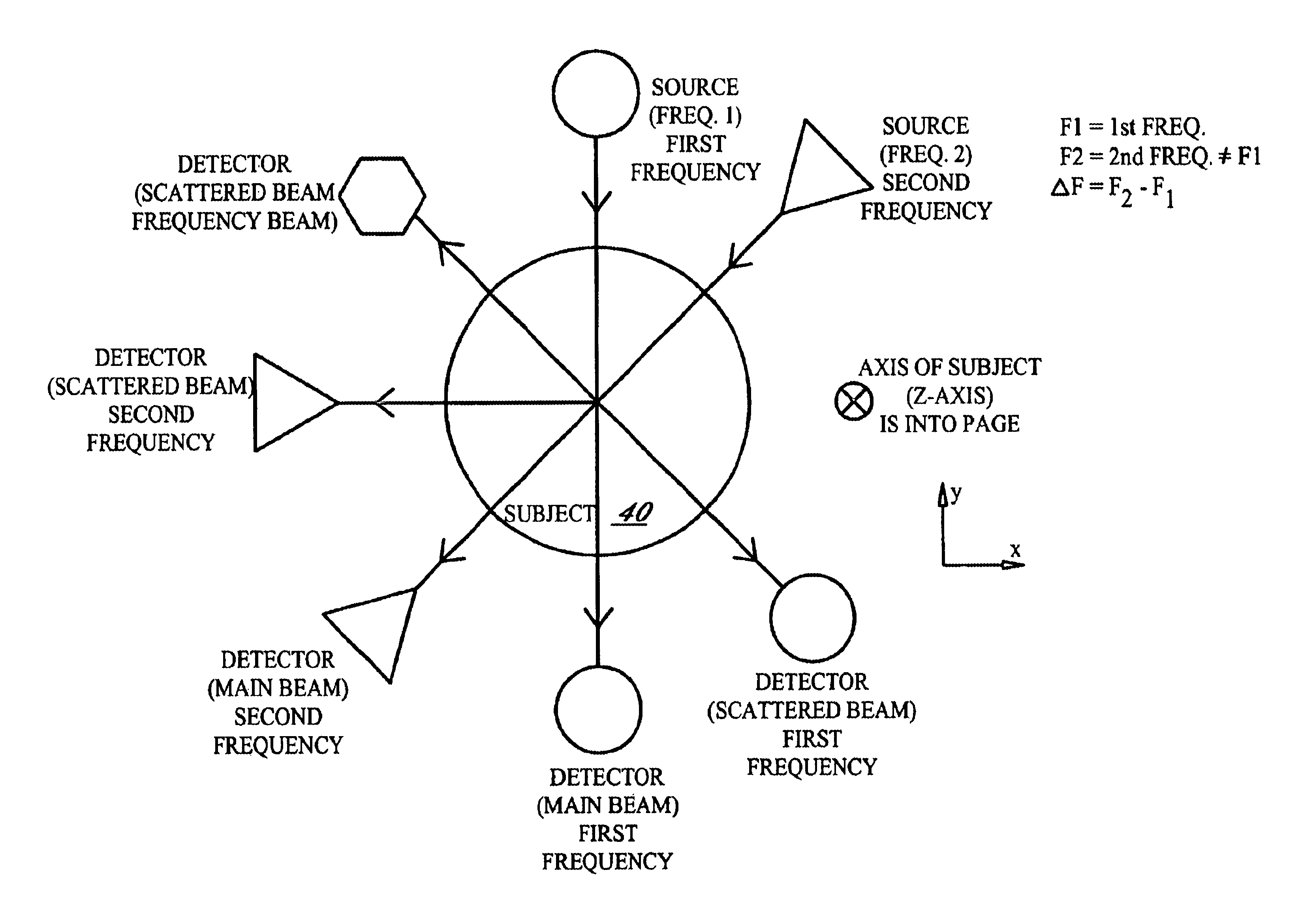
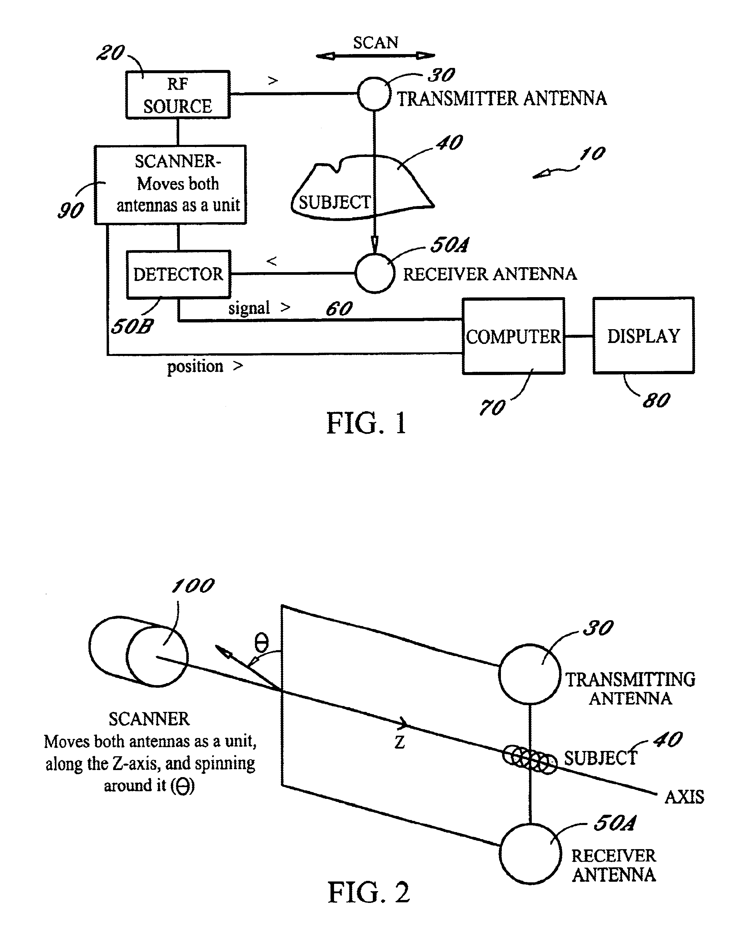
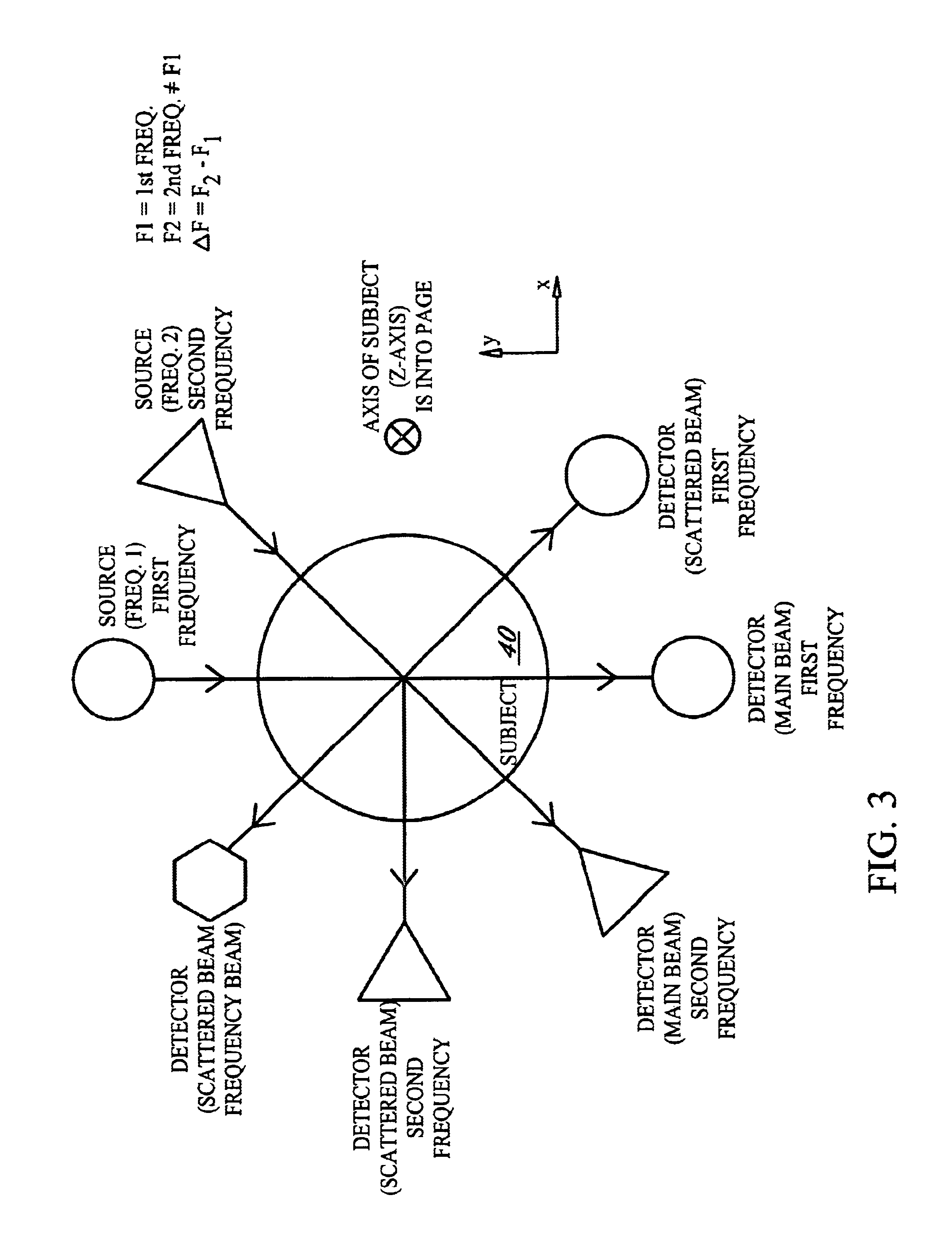
[0055]The present invention is a novel imaging system incorporating a Radio-Frequency source (for example a 10 gigahertz klystron), which is used to excite an antenna (for example a resonant cavity with an aperture), which allows RF energy to be emitted from this antenna. In one embodiment a standard horn or parabolic reflector antenna is used to create a spatially broad, perhaps substantially uniform RF field, with approximately plane parallel wavefronts in front of the antenna. In another embodiment, the aperture of the antenna is so small that only a small percentage of the applied RF “leaks” from the opening, creating circular wavefronts, emanating from the aperture. This RF then propagates through the subject to be received by a very small receiving antenna, in one embodiment a resonant cavity with a small aperture (less than a wavelength in extent in most instances). The straight line from the transmitting antenna to the receiving antenna defines a “beam” through the subject. ...


PUM

PropertyMeasurementUnit
diameteraaaaaaaaaa
internal structureaaaaaaaaaa
wavelengthaaaaaaaaaa

Abstract

An imaging system for medical and other applications in which the internal structures of an overall object must be seen without invading or damaging the object. The system works by transmitting electromagnetic waves of single or a multiplicity of frequencies through the object (for example the human body) and measuring the absorption and scattering of these waves by the various structures and inhomogeneities of the object, using scanning sub-wavelength resolution detectors.

Description

[0001]This application claims the benefit of and priority to U.S. Provisional Patent Application Ser. No. 60 / 268,169, filed Feb. 13, 2001.BACKGROUND OF THE INVENTION[0002]1. Field of the Invention[0003]The present invention relates to the field of imaging systems and specifically to an imaging system for medical and other applications in which the internal structures of an overall object can be seen without invading or damaging the object.[0004]2. Description of Related Art[0005]X-Rays using film and other detectors have had medical and industrial application for over one hundred years. Ultrasound has been used for certain medical and industrial applications for about 50 years. Computer-Aided Tomography (CAT) scanning (utilizing both ionizing radiation and radioactive tracers) and Magnetic Resonance Imaging (MRI) technology have been used for about 30 years. All of the ionizing radiation systems have dangers and risks associated with their use, particularly to human subjects. The MR...

Claims


Application Information

Patent Timeline
Patent Type & Authority Patents(United States)
IPC IPC(8): A61B5/05G01S13/00G01S13/89A61B5/053
CPCA61B5/05A61B5/0507G01S13/89G01S13/003A61B5/0536
Inventor GLEMAN, STUART M.
Owner GLEMAN STUART M
Why Eureka
Try Eureka