Photoacoustic breast imaging system and method

a breast imaging and photoacoustic technology, applied in mammography, medical science, diagnostics, etc., can solve the problems of reduced sensitivity in women with dense breasts, cancer-related deaths, and limitations of existing techniques for visualizing and diagnosing breast cancer, and achieves convenient correlation, high spatial resolution, and fast imaging capability.

Pending Publication Date: 2022-06-16
THE RES FOUND OF STATE UNIV OF NEW YORK
View PDF0 Cites 0 Cited by
  • Summary
  • Abstract
  • Description
  • Claims
  • Application Information

AI Technical Summary

Benefits of technology

[0004]Photoacoustic systems and methods with high spatial resolution, fast imaging capability, and convenient correlation is presented. The system can be used with all imaging modalities used for breast cancer detection—mammography, MRI, and ultrasound. The upright positioning allows for easy and quick patient imaging. Having light illumination from both sides of the breast stems the exponential decay of signal inside tissue to an extent, making it possible to get better images. Acquiring photoacoustic data from two transducers and combining it bolsters the signal intensity at the deepest portion of the breast where t

Problems solved by technology

It is the second leading cause of cancer-related deaths.
However, existing techniques to visualize and diagnose breast cancer have certain limitations.
Although mammogram is the most often performed standard procedure for screening, it has decreased sensitivity in women with dense breasts, along with exposure to ionizing radiation.
While Magnetic Resonance Imaging (MRI) has high sensitivity and specificity in dense-breast patients, it is very expensive and requires the use of intravenous contrast agents which can cause an allergic reaction, kidney damage, and permanent deposition in the central nervous system.
However

Method used


Image

  • Photoacoustic breast imaging system and method
  • Photoacoustic breast imaging system and method
  • Photoacoustic breast imaging system and method

Examples


example 1

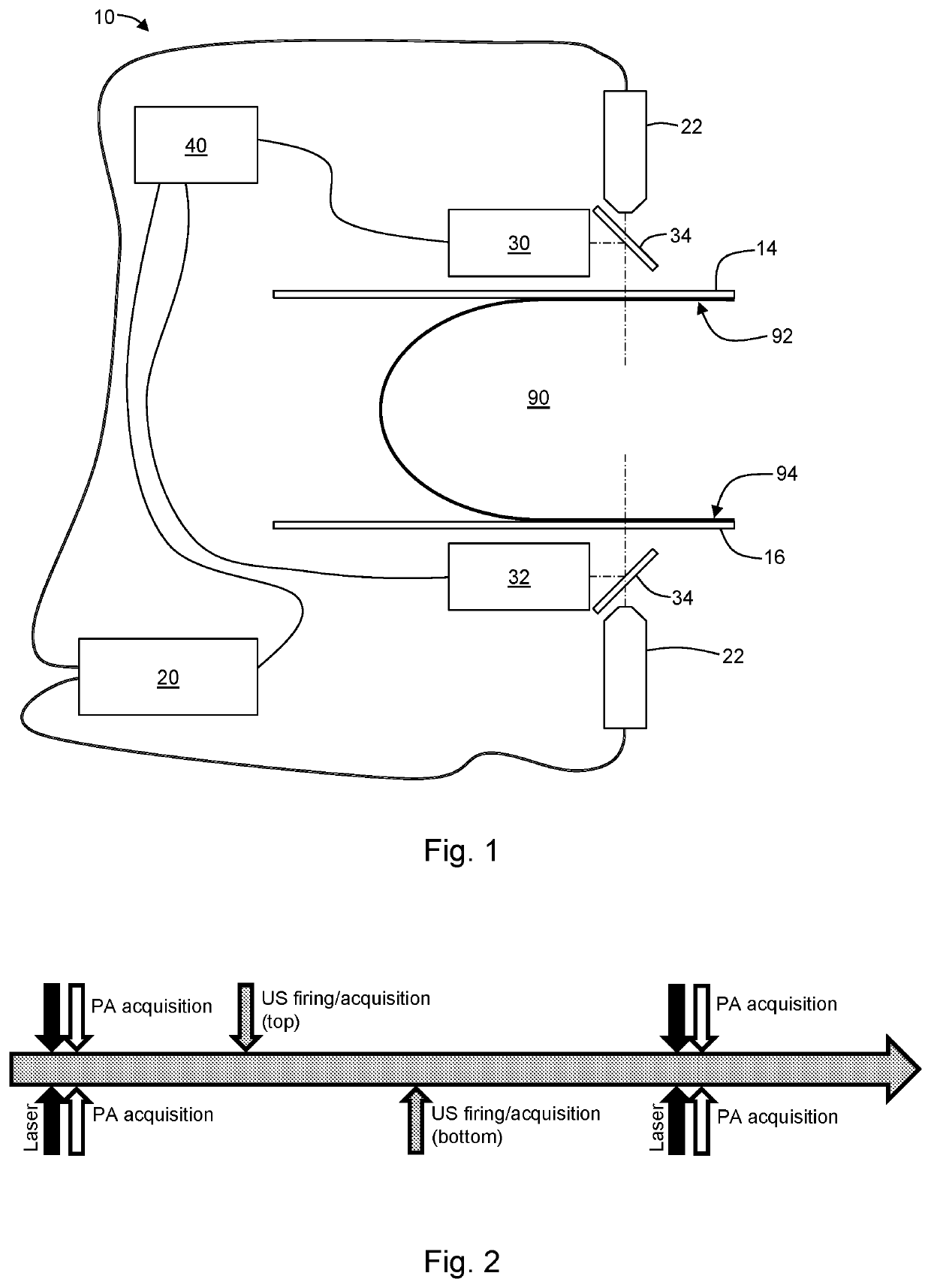
[0052]A system for imaging a sample, comprising: a pulsed light source configured to irradiate a region of interest in a sample from a first side and a second side opposite the first side; a first ultrasound transducer configured to receive acoustic waves induced at the region of interest and received from the first side of the sample; a second ultrasound transducer configured to receive acoustic waves induced at the region of interest and received from the second side of the sample; and a controller in electronic communication with the light source, the first ultrasound transducer, and the second ultrasound transducer, and wherein the controller is configured to: trigger a first light pulse from the light source; receive a first acoustic wave signal from the first ultrasound transducer, the first acoustic wave signal corresponding to the first light pulse; receive a second acoustic wave signal from the second ultrasound transducer, the second acoustic wave signal corresponding to t...

example 2

[0053]The system of Example 1, wherein the controller is further configured to: trigger a first acoustic pulse from the first ultrasound transducer; and receive a first echo signal from the first ultrasound transducer, the first echo signal corresponding to the first acoustic pulse.

example 3

[0054]The system of Example 2, wherein the controller is further configured to: trigger a second acoustic pulse from the second ultrasound transducer; receive a second echo signal from the second ultrasound transducer, the second echo signal corresponding to the second acoustic pulse; and wherein the second acoustic pulse is timed so as not to interfere with the first acoustic pulse and first echo signal.


PUM


Abstract

Systems and methods are provided for imaging a sample. The system may include a pulsed light source configured to irradiate a region of interest in a sample from a first side and a second side opposite the first side; a first ultrasound transducer configured to receive acoustic waves induced at the region of interest and received from the first side of the sample; a second ultrasound transducer configured to receive acoustic waves induced at the region of interest and received from the second side of the sample; and a controller.

Description

CROSS-REFERENCE TO RELATED APPLICATIONS[0001]This application claims priority to U.S. Provisional Application No. 62 / 826,979, filed on Mar. 27, 2019, now pending, the disclosure of which is incorporated herein by reference.FIELD OF THE DISCLOSURE[0002]The present disclosure relates to breast imaging, and in particular to photoacoustic breast imaging.BACKGROUND OF THE DISCLOSURE[0003]Breast cancer is one of the most common cancers—one in eight women will have the diagnosis during their lifetime in the United States. It is the second leading cause of cancer-related deaths. With the modern standard of care, early breast cancers detected by screening have achieved more than 99% five-year survival. However, existing techniques to visualize and diagnose breast cancer have certain limitations. Although mammogram is the most often performed standard procedure for screening, it has decreased sensitivity in women with dense breasts, along with exposure to ionizing radiation. While Magnetic Re...

Claims


Application Information

Patent Timeline
IPC IPC(8): A61B5/00
CPCA61B5/0095A61B5/4312A61B5/708A61B8/0825A61B8/4405A61B8/403A61B8/4281A61B8/4416
Inventor XIA, JUNNYAYAPATHI, NIKHILAZHANG, HUIJUAN
Owner THE RES FOUND OF STATE UNIV OF NEW YORK
Why Eureka
Try Eureka